Discussed in this report are the characteristics of and comparisons between Single Point Mooring (SPM) systems and Conventional Buoy Mooring (CBM) systems, also referred to as Multi-Buoy Moorings (MBM). These systems are used for short term mooring applications associated with the offloading and loading of bulk liquid fuel tankers transporting refined and unrefined products.
Permanently moored vessels are excluded from the scope.
1 Single Point Mooring System
(See our full detailed article on SPM CALM Systems)
An SPM is a loading buoy anchored offshore that serves as a mooring point as well as an interconnection for tankers loading or offloading liquid products.
The tanker is moored at the bow by means of one or two hawsers to the buoy. The vessel always takes the most favourable position in relation to the combination of wind, current and wave and is free to align itself with the prevailing environmental forces at the time. As the vessel in its stationary state is always positioned head-on into the winds/currents direction, the total force is less than would be experienced by a vessel on a fixed mooring which is not always head-on into the prevailing conditions.
The vessel will approach the buoy with its bow into the dominant environment, thus maximising control while minimising the need for tug assistance.
A tug is required at all times during mooring and offloading to maintain the nominal amount of tension on the mooring hawsers to prevent collision of the tanker with the buoy and assist with the weather vane of the vessel.
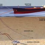
The fluid transfer system includes submarine hoses between the pipeline end manifold (PLEM) on the seabed and the buoy and floating hoses between the buoy and the tanker. The buoy contains a swivel that provides the fluid transfer path between the geostatic part and the rotating part of the buoy.
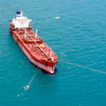
Refer to Figure 1 illustrating a vessel moored to an SPM system.
1.1 SPM Components
The SPM system consists of four main components:
- Buoy body
- Mooring and anchoring elements
- Product transfer system
- Ancillary Components

Figure 1: SPM system including moored vessel and connected floating hoses
1.1.1 Buoy Body
The buoy body is held in place by means of static legs attached to the seabed underneath the surface. The body has a rotating part above water level connected to the offloading/loading tanker. These two sections are linked by a roller bearing, referred to as the Main Bearing. The moored tanker can freely weathervane around the buoy and find a stable position due to this arrangement.
The type of bearing used and the split between the rotating and geostatic parts determine the concept of the buoy. SPM mooring concepts are distinguished in Table 1.
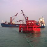
The size of the buoy is a function of the counter buoyancy needed to hold the anchor chains in position, and the chains are a function of the environmental conditions and the vessel size. Figure 2 illustrates a Turntable type SPM system during installation.
1.1.2 Mooring
Moorings fix the buoy to the seabed. The type of anchoring system is greatly dependent on local soil conditions and may consist of ships-, rig-, piles- or gravity anchors.
The two main types of mooring configurations for SPMs are Catenary Anchor Leg Mooring (CALM) and Single Anchor Leg Mooring (SALM). CALM holds the buoy in place by anchor chain that extends in catenaries to anchor points some distance from the buoy.
The SALM system is similar, except that the SALM is anchored by a single anchor leg. The primary benefit of a CALM Buoy over a SALM Buoy is ease of maintenance. The vast majority of Marine Terminals installed since the mid-1990s have been CALM Buoys. Figure 3 illustrates the CALM Buoy type concept.
Mooring components of a CALM system:
- Anchors (piles- or gravity anchors connects the mooring chain to the seabed)
- Anchor chain (systems with six or eight anchor chains are the most common)
- Chain stoppers (connects the chains to the buoy)
Figure 2: SPM (Turntable) being towed into position

Figure 3: SPM CALM Buoy system configuration
1.1.3 Product Transfer System
The heart of each SPM is the product transfer system. This system transfers products from the tanker to the PLEM located on the seabed.
The basic product transfer system components are:
- Flexible subsea hoses also referred to as Risers which connects the PLEM to the Buoy. The configuration varies on depth, sea state, buoy motions, etc. and can take the form of a Chinese lantern, lazy-s, lazy wave or steep-s
- Floating hose strings which connect the buoy to the tanker.
- Marine breakaway coupling which allows for emergency disconnection of the pipeline to prevent rupture of hoses/hawser and subsequent oil spills.
- Product swivel, valves and piping connecting the geostatic and rotating parts of the buoy and enables the tanker to rotate with respect to the mooring buoy.
1.1.4 Ancillary Components
Other possible components of SPMs are:
- A boat landing, providing access to the buoy deck.
- Fenders to protect the buoy.
- Lifting and handling equipment to aid materials handling.
- Navigational aids for maritime visibility, and foghorn to keep moving vessel alert.
- Electrical subsystem power navigation aids or other equipment. Electrical power can be provided either by batteries which are recharged on a regular basis or solar power systems to maintain the charge in the battery packs.
- Options are available for a hydraulic system to allow the remote operation of the PLEM valves if required.
1.2 Operating Constraints
1.2.1 Vessel Size
There are no vessel constraints for an SPM. The SPM CALM buoy configuration can accommodate the largest vessels, including VLCCs.
1.2.2 Depth
SPM CALM buoy systems are suited for locations up to approximately 100 m water depth. This is preferential when deep waters are not available close to shore.
The minimum depth is a constraint for the design vessel Under Keel Clearance (UKC).
1.2.3 Mooring
- Possible to moor with winds up to 30 knots and head waves of 2.0 m to 2.5 m.
- The vessel has to leave berth when winds exceed 60 knots and waves are higher than 3.5 m to 5.0 m.
- Approach to the SPM can be from any direction (from a mooring perspective).
- Mooring typically takes 15 min. (once the vessel has arrived at SPM).
- Disconnecting from mooring does not necessarily need tug assistance, although tugs may be required depending on the local site condition and availability of space for vessel manoeuvring.
- Disconnecting from mooring typically takes 15 min.
1.2.4 Offloading
- Hose connection typically takes 1 hour.
- Hose disconnection typically takes 1 hour.
- Product unloading possible with winds up to 40 knots and head waves of 3.0 m to 4.5 m.
- Fulltime tug required to assist with weather vane and prevent collision between the vessel and the SPM.
- Typically, vessels are only able to offload a single product at a time, however, SPMs can be designed to handle multiple products if required.
2 Conventional Buoy Mooring System
Conventional Buoy Mooring (CBM) or Multiple Buoy Mooring (MBM) is a mooring facility consisting of three to eight permanent mooring chains with anchors. It holds the vessel in a fixed position and does not allow it to weathervane. A buoy is attached to the end of each chain to mark the position of the chain and allow pickup of the chain by the vessel to be moored.
The number of mooring chains is a function of the vessel size, metocean conditions and navigational constraints.
As soon as the tanker has manoeuvred into position with the aid of tugs, a launch crew takes the tanker lines, one at a time, and tows them to the various mooring buoys.
When berthed, the tanker remains in a fixed position without tugs and depending on the site-specific conditions, sometimes without vessel anchors.
The ships’ mooring ropes are connected from either side of the vessel from the bow and the stern to quick release hooks on the conventional buoys.
After mooring the tanker to the buoys, pickup of the submerged hose strings and connecting the hoses to the midship manifold, the loading or offloading operation may start. The other end of the hose string is connected to the PLEM.
The tanker needs assistance in disconnecting from the mooring and navigating away from the CBM system. Figure 4 is a representation of a general CBM system.

Figure 4: CBM system (four conventional buoys)
2.1 CBM Components
2.1.1 Buoys
The buoys in a CBM system are conventional in that they act as mooring only structures. They contain no product transfer paths.
The size of the buoys is a function of the counter buoyancy needed to hold the anchor chain for each buoy in position.
The buoys are manufactured either from steel or polymer materials.
2.1.2 Mooring
The mooring system comprises of Mooring Buoys and Mooring Legs, where the buoys are generally moored to the seabed with chain legs and high capacity anchors, piles or clump weights depending on soil characteristics.
A typical CBM system’s buoys have mooring assemblies through the centre of the units, terminating in a mooring eye on the bottom and padeyes on top for the fitting of quick release hooks
The mooring legs for each buoy only consists of one anchor, unlike in the case of a CALM system where the buoy has between six and eight anchors. This is because the anchor chains of a CBM system only needs to work in one direction.
2.1.3 Product Transfer
- The product transfer system for CBMs consists of:
- Offloading hoses (connects the tanker to the subsea PLEM).
- Marine breakaway coupling (which acts as a weak link and prevents rupture of hoses/hawser and subsequent oil spills).
When the system is not in use, the hose string is laid down on the seabed away from the influence of the waves. The end of the hose is provided with a pick-up line and a marker buoy. The hose string is picked up by a small support vessel that also assists the tanker with mooring to the buoys. CBMs can be operated with up to four separate product lines
2.2 Operational Constraints
2.2.1 Vessel Size
As no weathervaning is possible, it is often applied on projects where smaller tankers are employed, in areas where the environmental conditions are moderate or uni-directional and where the frequency of loading/offloading operations is limited.
The system can be designed to berth all sizes of tankers, with the largest CBM system in the world designed to accommodate vessels up to 225 000 dwt (Puma multi-directional loading facility, Angola, 2015).
2.2.2 Depth
CBM systems are ideally suited to shallow water applications up to approximately 30m water depth, in benign environmental conditions or conditions with a dominant directional character.
The minimum depth is a constraint of the design vessel UKC.
2.2.3 Mooring
- Possible to moor with winds up to 30 knots and head waves of 1.0 m.
- The vessel has to leave berth with winds of 60 knots and waves higher than 2.0 m to 3.0 m.
- Mooring typically takes 2 hrs (once the vessel has arrived at CBM).
- Disconnecting from mooring typically takes 1.0 hrs.
2.2.4 Offloading
- Hose connection typically takes 1.0 hrs.
- Hose disconnection typically takes 1.0 hrs.
- Product unloading with winds up to 40 knots and waves higher than 2.0 m to 2.5 m.
The offloading/loading operations can be undertaken via a number of hoses (one to four hoses) and can handle multiple products if required.
3 Comparison Summary
| CRITERIA | SPM | CBM |
| Vessel size | Vessel sizes unlimited | Vessel sizes typically up to 80 000 dwt, but up to 225 000 dwt has been installed |
| Operating water depth | Up to 100 m water depth | Up to 30 m water depth |
| Mooring chains | 6 to 8 mooring chains | 4 to 8 mooring chains |
| Approach | Can approach from any position – and therefore can choose to approach into prevailing weather conditions | Can only approach from limited positions |
| Mooring time (after arriving at mooring position) | Typically 15 min. | Typically 2.0 h |
| Hose connection time | Typically 1.0 h | Typically 1.0 h |
| Offloading time | The function of vessel pumps capacity, line size and distance | The function of vessel pumps capacity, line size and distance |
| Hose disconnection time | Typically 1.0 h | Typically 1.0 h |
| Mooring disconnection time | Typically 15 min. | Typically 1.0 h |
| Net total time difference | Typically 2.5 h quicker compared to CBM | Typically 2.5 h longer compared to SPM |
| Mooring conditions | Able to moor with winds up to 30 knots and head waves of 2.0 m to 2.5m | Able to moor with winds up to 30 knots and head waves of 1.0 m |
| Offloading steps | Steam from anchorage, moor, connect hoses, pump product through, disconnect hoses, disconnects mooring, steams away | Steam from anchorage, moor, connect hoses, pump product through, disconnect hoses, disconnects mooring, steams away |
| Operating limit | Product offloading possible with wind up to 40 knots and head waves of 3.0 m to 4.5 m | Product unloading with wind up to 40 knots and waves higher than 2.0 m to 2.5 m |
| Mooring disconnection | The vessel has to leave berth with winds of 60 knots and waves higher than 3.5 m to 5.0 m | The vessel has to leave berth with winds of 60 knots and waves higher than 2.0 m to 3.0 m |
| Cost | Approximately US $15m for SPM CALM buoy alone | Approximately US $120k to $ 250k per buoy alone |
| Tuggage | Required for mooring. Tug required full time during mooring to assist with weathervane movements | Required during mooring and disconnection from moorings |
| Under Keel Clearance | The function of the vessel and metocean conditions | The function of the vessel and metocean conditions |
| Suppliers | Proprietary technology and limited suppliers | Non-proprietary technology |
| Track record | Since 1959 successfully installed around the world | Successfully installed around the world for close to a century |
| Weather impact | Less prone to adverse conditions and swell delays than a CBM | More prone to adverse conditions and swell delays than an SPM |
| Night operations | Possible limitation on night-time mooring depending on local operational, safety and environmental procedures. Can disconnect from moorings 24 h a day | Possible limitation on night-time mooring and disconnecting from mooring depending on local operational, safety and environmental procedures |
| Maintenance | Additional complex maintenance activities compared to a CBM – swivel, bearings, mooring line tensions, etc. | Less complex maintenance compared to SPM. Hoses damage more due to abrasion from storage on the sea bed |


 To all knowledge