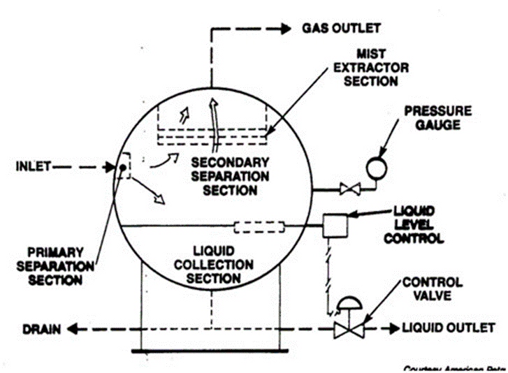
The separator is the pressure vessel that separates the liquid and gaseous constituents. For example, at the wellhead, hydrocarbon streams are composed of gas, liquid hydrocarbons, and free water. Most of the time, dividing these stages as soon as possible is preferable so that the two or three phases may be tackled independently. In a broader way and based on the type of separated streams, separators are categorized into two types: gas/liquid two-phase separator and gas/oil/water three-phase separator.
1 Separator Types
Separators may be of different sizes and geometry, but their main function always remains same. They are employed to divide the constituent that flow into them. Separators can be categorized according to layout or fluid flow.
1.1 Vertical Separator
A vertical separator is frequently utilized when well streams have a low/moderate gas-to-oil ratio, and a large liquid slug is anticipated. The action of the liquid level control is not as crucial since it can handle greater slugs of liquid without leaking into the gas exit. Due to the greater vertical separation between the liquid level and the gas outlet, the liquid is less likely to re-vaporize into the gas phase. A vertical divider is essential when restricted space/area is available on an offshore platform since it takes up less floor space.

Figure 1: Verticle Separator Schematic
1.1.1 Advantages
- The substantial vertical distance between the liquid level and the gas outlet limits the possibility of the liquid re-vaporizing into the gas phase
- There are fewer entrainment tendencies
- Surge control is an additional advantage
1.1.2 Disadvantages
- Reaching some equipment and safety devices may be challenging without ladders or access platforms
- For a similar gas capacity as the horizontal separator, a separator with a wider diameter is needed
1.2 Horizontal Single Tube Separator
The horizontal separator consists of the huge, long, baffled gas-separation portion that enables greater gas velocities and has a significantly bigger gas-liquid contact surface. The huge liquid surface area makes it possible to extract gas from the liquid effectively. This vessel offers a sizable interface area between the liquid and gas phases, enabling more separation capability when gas capacity is a design consideration. The horizontal vessel is more economically viable in high-pressure separators since larger diameters necessitate thicker walls.

Figure 2: Horizontal Single Tube Separator Schematic
1.2.1 Advantages
- They have a higher liquid/gas interface because of a large, protracted, and baffled gas-separation component
- The price of the horizontal separator is lower than that of the vertical separator
1.2.2 Disadvantages
- Level control is critical and should be maintained
- Cleaning is challenging
1.3 Double Tube Horizontal Separator
A typical horizontal separator’s advantages are included in a horizontal double-tube separator, with a greatly increased liquid capacity. It features two vessels positioned horizontally and vertically. The synthesized fluid enters the top vessel, where baffles separate it into liquid and gas. When the liquid reaches the bottom vessel, it separates from the oil. More produced fluids may be processed by a horizontal separator having two barrels than by one.

Figure 3: Schematic of Double Tube Horizontal Separator
1.3.1 Advantages
- This equipment is helpful in case of high gas flow rates and a chance of large liquid slugs
- It makes it easier to deal with liquid floods
1.3.2 Disadvantages
- It involves additional costs
1.4 Spherical Separator
Vertical separators also include spherical separators. This design is low cost and consists small vessel configuration. They are inefficient when a well stream is subjected to surging foamy components or has excessive muck or sand. These separators are no longer often utilized because of their drawbacks.

Figure 4: Schematic of Spherical Separator
1.4.1 Advantages
- It is economical
- It is advantageous for low or moderate gas-to-oil ratios
- It is portable and straightforward to set up
1.4.2 Disadvantages
- Liquid level management affects how well the spherical separator performs.
- Both the liquid settling portion and surge capacity have deficient capacities.
- It is challenging to use in three-phase due to the limited interior area (water, gas and oil).
1.5 Other Separator Types
- Cyclone/centrifugal separators
- Filter separators
- Scrubbers
2 Separator Design and Associated Factors
A separator’s functioning and ability to separate the liquid and gas phases depend on several fundamental variables:
- Operating temperature of the separator
- Operating pressure of the separator
- Fluid stream composition
The amount of gas and liquid exiting the separator will change if any of these variables changes for a particular fluid well stream. The well stream composition is a natural reality in most cases, and the operator has little influence over it.
Gas Capacity and Liquid Capacity calculation for a separator are important, and the main contributor to which procedure is given here:
Gas Capacity
The gas capacity of oil-gas separators is usually calculated using Souders-empirical Brown’s relationship:

Where;
v = Gas speed at the surface
A = Cross-sectional area separator area for vapor flow
q = Gas flow rate
ρL= Liquid density
ρg= Gas density
K = Empirical factor (value varies from 0.12 to 0.35, depending on the type of separator)
Liquid Capacity
The main factor that changes how much liquid a separator can hold is how long the liquid stays in the vessel. A good separation needs enough time for the liquid and gas phases to reach a state of equilibrium at the temperature and pressure of separation. The following equation can determine how much liquid a separator can hold or how much settling volume is needed based on retention.

Where;
W = Liquid capacity
V = Liquid settling volume
t = Retention time
3 References
- Sivalls, C. R. (1987). Oil and gas separation design manual. Sivalls Incorporated.
- Stewart, M., & Arnold, K. (2008). Gas-liquid and Liquid-liquid Separators. Gulf Professional Publishing.
- Tarleton, S., & Wakeman, R. (2006). Solid/liquid separation: equipment selection and process design. Elsevier.

 To all knowledge