1 Introduction
1.1 Pipeline Pigging System
The Pipeline pigging system is the process of using a device referred to as Pig to perform various tasks including cleaning, maintenance, inspection, batching, dimension check on a new or existing pipeline. During pigging operation of an existing pipeline, pipeline operations are not stopped, meaning the pigging tool is introduced into the flow stream and travels along the pipeline utilising the flow and pressure of the pipeline.
It should be noted that pigging operation is performed on gas pipelines, liquid hydrocarbon pipeline, pipelines conveying waters, pipelines transporting slurries, etc.
Pigging operations are performed using Pig Traps (Launcher and Receiver), a Pigging tool and a medium for propelling the pig in the pipeline.
A pipeline may be equipped with permanent pig launchers and receivers; however, the use of temporary launchers and receiver is common. Temporary launchers are typically utilised for subsea pipeline pigging, the launcher is connected to the pipeline end manifold for the commencement of pigging operation.
Pigging operation is a critical activity that should be appropriately planned, taking all safety and operational considerations into account. Several accidents have been recorded during pigging operations.
This article will lay more emphasis on pigging facilities installed within onshore and offshore platforms.

Figure 1: Arrangement of Pig Launchers and Receivers in a Facility
2 Pigging Pigging System: Operation Major Component
2.1 Pig Traps
Pig traps are static equipment utilised for the introduction of pigging tools into a pipeline and receiving the pigging tool at the other end of the pipeline. There are two types of Pig Traps
2.1.1 Launcher
The Launcher is the equipment where the pigging tool is fed into the pipeline. It comprises a door or end closure which can be opened and closed. There are nozzle connections on the Launcher. These will be discussed in later sections of this article
2.2.2 Receiver.
The Receiving Trap is stationary equipment used for receiving the launched pigging tool. Generally, they almost look the same as the launcher except for some configuration changes. The Receiver is equipped with a door or an end closure, this is where the pigging tool and cleaning debris are received. There are nozzle connections to the receiver for piping and instrumentation connections, these will be discussed in details in further sections in this article.
2.2.3 Pig Trap Orientation
Generally, a pig trap may be installed in any of the below orientations. The major factor dictating the type of orientation is the space available. In offshore application riser location and entry position into the platform is a key factor.
2.2.3.1 Vertical launcher
A vertical launcher is specifically for launching with a short neck and a concentric reducer. These launchers orientation are used in offshore platforms where space availability is critical. Also, the pipeline riser is vertical so in some cases the vertical configuration is the best by aligning the Launcher to the Riser
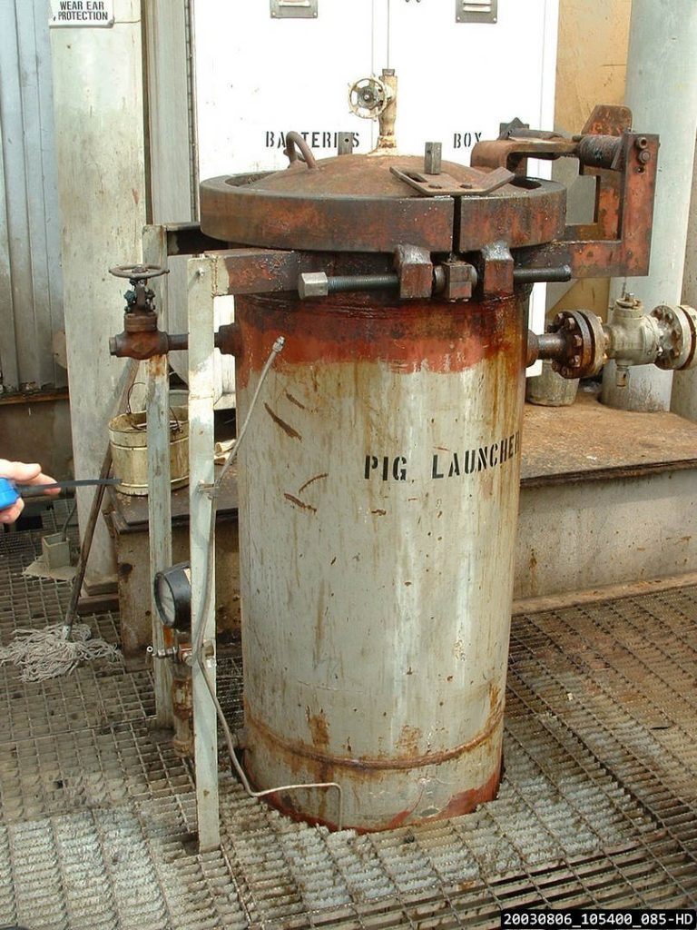
Figure 2: Vertical Pig Launcher Installed on Offshore Platform. Launcher
2.1.3.2 Vertical receiver
Vertical receivers are specifically for receiving with a longer neck and a concentric reducer. They are not very common, however, they are used mostly in offshore applications. Just like the vertical Launchers, there are more applicable when there are space limitations. It should be noted that the use of vertical pig receiver is prohibited by some companies.
2.1.3.3 Horizontal launcher
These types of Launchers are specifically for launching in the nearly horizontal position. They have an eccentric reducer (Flat on Bottom) to ensure the pig enters the neck in the correct orientation. These launchers are the most commonly seen in all facilities. They can be conveniently installed onshore and on offshore platforms where there is no space limitation.
It should be noted that some Companies regulations require that horizontal Pig Launchers should slope downward toward the pipeline, the essence of this slope is to aid liquid draining from the barrel. As per SHELL DEP 31.40.10.13-Gen, the minimum slope angle required for pig launcher is 3 degrees
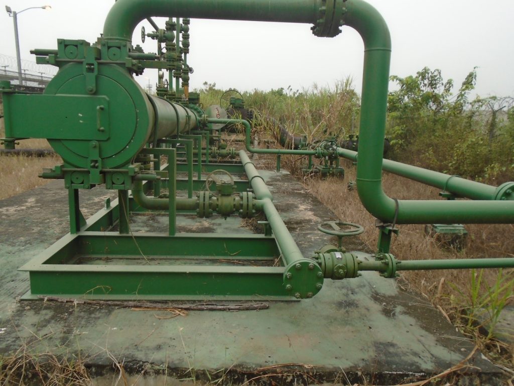
Figure 3: Horizontal Gas pipeline Pig Launcher
2.1.3.4 Horizontal receiver
These Receivers are specifically for receiving pigging tools in the horizontal position. It could either have a concentric or eccentric reducer, however, the eccentric reducer type is the most common.
They are the most common type of reducers, they can be found in offshore platforms and onshore facilities.
Some Companies regulations require that horizontal Receivers should slope downward toward the end closure, the essence of the slope is to aid liquid draining from the barrel. As per SHELL DEP 31.40.10.13-Gen the minimum slope angle required for pig launcher is 3 degrees

Figure 4: Horizontal Gas Pipeline Pig Receiver
2.2 Pipeline Pigging tool
A pipeline pig or pigging tool is a device driven through a pipeline by the flow of the fluid (Flowrate and Pressure) within the pipeline and that is used to perform various internal activities. These activities include cleaning, separation of pipe fluids (batching), internal inspections, dimension checks etc. Various types of pigging tools are available with various applications they may be grouped based on function, the material of construction and applications. Some example of pigging tools are listed below
- Foam Pigs
- Spherical Pigs (Spheres)
- Steel Mandrel pigs
- Solid Cast Pigs
- Geometry/Calliper pigs (Inline Inspection Pigs (ILI))
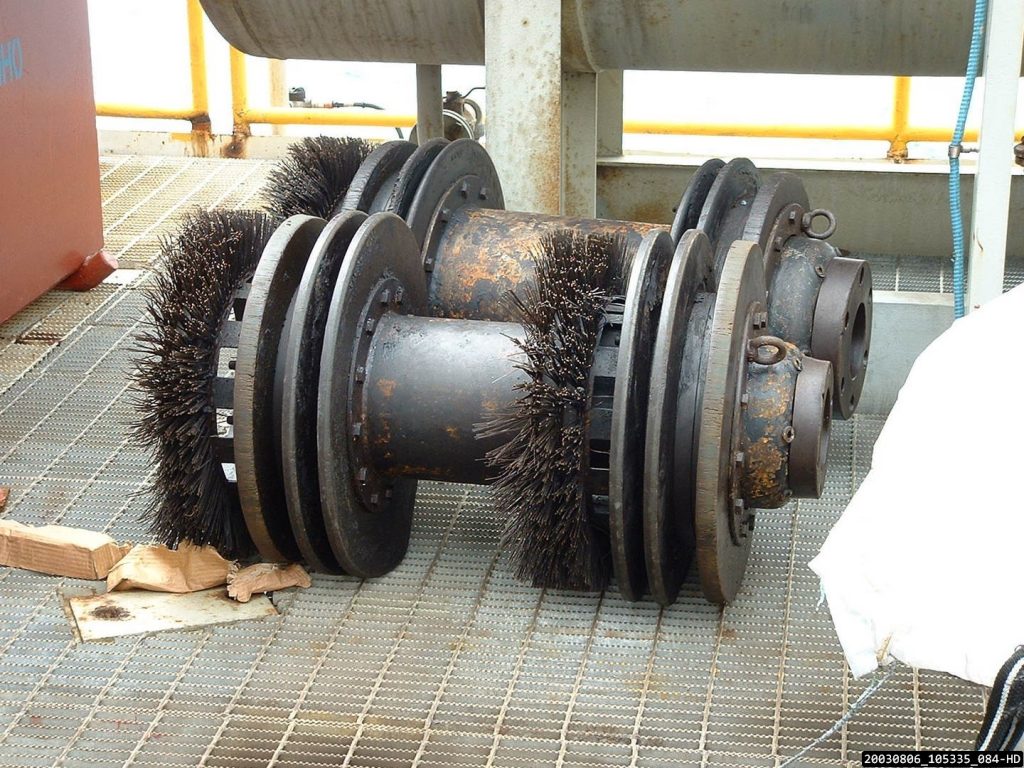
Figure 5: Pigging tool with Brushes Utilised for Cleaning a Subsea Pipeline offshore
3 Pipeline Pigging System: Operations and Applications
As stated in section 1.0 pigging operations are performed for specific reasons. Some pigging operations are highlighted below
3.1 Cleaning Operations
This is one of the major pigging operations. It is used for existing pipelines i.e. pipeline in service, newly constructed pipelines with debris resulting from welding and construction activities.
Pipeline conveying fluids (Liquid and gas) over time accumulates debris which may have resulted from the fluid transported, internal corrosion, Wax formation etc.
Pipeline usually have debris due to welding and other activities during pipeline constructions.
Debris can be effectively removed by sending a suitably selected pig through the pipeline. For an in-service pipeline, the flow operation conveys the pig across the entire pipeline length to the receiver.
For new pipeline under construction prior to commissioning compressed air could be used to propel the pig across the entire length of the pipeline.
Various types of pigs could be utilised for this operation including Steel Mandrel pigs, Solid cast pigs. However, Steel Mandrel and Solid Cast pigs perform much more efficiently.
3.2 Pipeline Dewatering
Dewatering entails the removal of water from a pipeline. This activity is usually performed after a pipeline has been hydro tested. After hydro test all the water in the pipeline cannot be drained due to varying elevation along the pipeline. A Pig is sent into the pipeline to perform the function of pushing most of the water out. Foam pigs are mostly used for this task.
Dewatering is performed by propelling a pig through the entire pipeline. Compressed air at appropriate pressure is used to drive the pig while the trapped water in the pipeline is pushed out.
It should be noted that this activity may be repeated more than once to ensure that the pipeline is thoroughly dewatered.
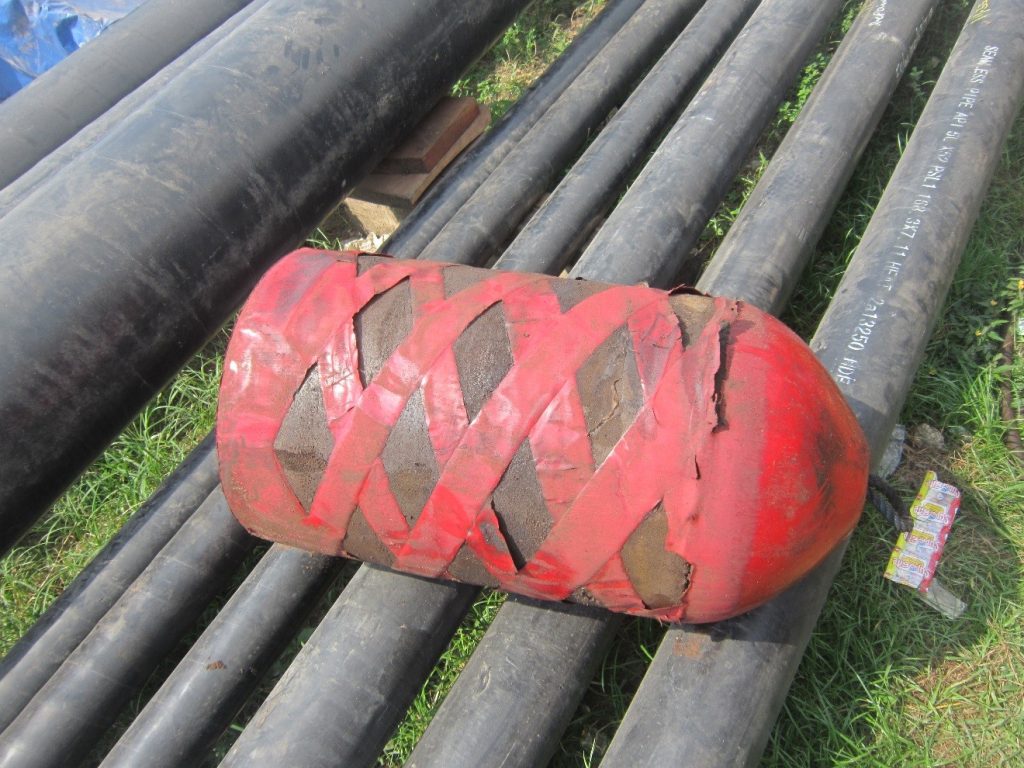
Figure 6: Foam pig Used for Dewatering Operation
3.3 Geometry or Calliper Pigging
This is another pipeline pigging operation performed during pipeline construction activities or after sections of the pipeline has been replaced. It may also be carried out on the suspicion of pipeline defects.
These tools can effectively measure pipeline internal bore diameter, depth of dents, bend radius, ovalities, deformations, girth weld etc.
The aim of this activity is to detect pipeline imperfections exceeding the maximum code allowable. Geometry pigs may be propelled using compressed air.
This tool has inbuilt global positioning system, this help to give the accurate location of any measured data.
3.4 Batching Operation or Sealing Operation
There are pipelines designed and constructed to convey more than one type of product (multi-product pipelines). A pipeline can be designed to transport ATK (Aviation Turbine Kerosene) and DPK (Dual Purpose Kerosene), Premium Motor Spirit (PMS) and Automotive Gas oil (AGO) etc.
These products are transported in batches i.e. ATK before DPK.
The operation is performed by using a sealing pig to form a barrier between the two fluid been transported. This type of pigging operation utilises the system flow parameters (flow rate and pressure) to propel the pig through the pipeline. At the reception facility, the interface zone between batched fluids is sent to a slop tank for further process activities.
Foam pigs and other solid pigs are ideal for batching operations.
3.5 Pipeline Inspection Pigging Operation.
This is an advanced type of pigging operation performed by using inspection tools also referred to as smart pigs or in-line inspection pigs.
These pigs are used to acquire information especially the corrosion rate of the pipeline. They are also be used to measure the curvature of the pipeline, the diameter of the pipeline (internal and external).
As the pigging tool is propelled along the pipeline the characteristics of the pipeline is measured, these results are further interpreted and analysed to obtain various data.
This method of pigging is utilised for the in-service pipeline, the pigging activity utilises the fluid flow parameters (flow rate and pressure)
Generally, two types of inspection methodology are employed as discussed below:
3.5.1 Magnetic Flux Leakage (MFL)
MFL pigging tools utilise magnetism to detect wall thickness loss in pipelines by using a very strong magnet to magnetise the pipe wall. Metal-loss in the pipe wall due to corrosion or other factors will cause a change in the induced magnetic field. Changes in pipe wall thickness can be sensed using a detector hence corrosion or loss of metal can be detected.
The data collected can be further analysed to obtain other data such as bends angles etc. Magnetic flux leakage pigs can be utilised for both gas and liquid pipeline.
3.5.2 Ultrasonic Inspection
This method utilises ultrasound to measure pipeline wall thickness. As the pig is propelled through the pipeline a transducer transmits signals perpendicular to the pipe wall surface, these signals are received for each position of the pig along the pipeline by the transducer. The signal received is from both the internal and external wall of the pipeline.
The time taken to receive the signal is further analysed to determine the pipeline wall thickness.
It should be noted that Ultrasonic pigs are applicable to the liquid pipeline system.
A major advantage of Ultrasonic inspection over Magnetic Flux Inspection is its ability to measure the higher wall thickness of pipelines.
4 Pipeline pigging system philosophy
During pipeline planning stage a pigging philosophy should be developed. The philosophy shall cover activities including pipeline cleaning, pipeline wall thickness inspection. Requirements for pigging equipment are stated in section 864.2.3 of ASME B31.8. Some of the considerations for developing the philosophy are stated below.
4.1 Pigging Philosophy Considerations
4.1.1 Planned Type of Pigging Operation
This is one of the key factors to be considered when developing a pipeline pigging philosophy. This is a function of the fluid characteristics (Corrosive or non-corrosive) and other factors. Pipeline transporting non-corrosive fluids will be less subjected to internal corrosion hence the need for intelligent pigging is lesser than pipeline transporting corrosive fluids.
Pipeline transporting sensitive fluids such as Aviation fuel require regular checks to detect contamination of fuel due to corrosion and debris. This is usually tackled by the selection of appropriate pipeline material and pipeline inspection plans during the pipeline planning stage.
The operations to be performed over a period of time should be well detailed in the philosophy and judiciously implemented during the operation phase of the pipeline.
4.1.2 Frequency of Pigging Operation
This is usually considered during the development of the pigging philosophy. Depending on the fluid characteristics been transported the frequency of pigging operation varies.
Pipelines transporting corrosive fluids have a higher frequency of inspection compared to pipeline transporting non-corrosive fluids.
Pipelines used for Batching operation (multi-product pipelines) require frequent use of batching pigs. This should be carefully planned based on the volume of fluid been transported and the frequency of transporting a different product.
4.1.3 Selecting Appropriate pigging tool
There are many manufacturers of pigging tools, however, during the pipeline planning stage, it is important a manufacturer or two is selected. It is important to select manufacture because different vendors have a different specification for their pigging tool. The pigging tool specification may include:
- The length of the pig
- Pigging tool operational weight
- Pigging tool transportation weight
- The maximum inspection ranges of the pigging tool
- The velocity range required for the pigging tool
- Maximum and minimum operating pressure for the pigging tool
- The product temperature range the pigging tool can be used
Keeping in mind the above requirements a particular pigging tool is selected to satisfy the fluid properties and the pipeline is designed to suit the dimensional requirements of the pigging tool.
4.1.4 Planning for Debris Handling
When preparing the pigging philosophy there should be an estimation of the quantity of debris expected from pipeline pigging operation. Appropriate provision for handling and disposing of this debris should be well spelt out.
4.1.5 Pig Tracking
It is paramount that when a pig is launched the location of the pig is known. There are instances that pigging tools get stocked in a pipeline. It is there very important to know the actual location of the tool to proffer remedial actions in the event that a pig did not arrive at the proposed destination. Smart pigs are easily tracked because they have in-built monitoring system which can be used to determine the location of the pig. The pigging tool has inbuilt transmitters which send out a signal at a variable frequency to a receiving system.
4.2 Factors Affecting Pigging Tool Selection
There are several factors affecting pigging tool selection, some factors will be highlighted in this section. During the pipeline planning stage of a pipeline, pigging should be a critical part of the project that must be properly analysed.
4.2.1 Pipe Size
When selecting the pigging tool the size of the pipeline is a major factor. Intelligent pigs have minimum and maximum operational pipeline size which they can operate effectively.
Also the bigger the pipeline the bigger the tool. The size of the tool affect the operational effectiveness of attachments such as brushes’
Also, larger tools are subject to higher stresses.
4.2.2 Pipeline Length
Pipeline length varies, the length of the pipeline affects the operational efficiency of the pigging tool. Foam pigs used on long pipelines are subjected to more frictional wear.
Smart pigs usually have the maximum specified pipeline length that can be covered. Also due to the friction between the pigging tool and the pipeline wall, there is a tendency of more heat generated during the pigging of long pipelines. It is there for paramount to select a tool that satisfies the pipeline length requirement.
4.2.3 Pig Handling Area Available
During pigging operation space is required to convey the pigging tool close to the barrel, above the barrel for vertical launchers and receivers. Space requirement is more critical when pigging with smart tools due to their size. Usually, pig tool manufacturer specifies the minimum area required for pigging operation. Also, the handling area should also take into consideration the radius required for the safe operation of the pig trap end closure.
It is, therefore, necessary that the available space required for pigging operation is created around the trap or the pig tool selected can be successfully operated within the available space.
4.2.4 Bend Radius
This a major factor that affects pigging when smart pigs are used. Smart pigs are longer than conventional cleaning and batching pigs. They are flexible to navigate pipeline bends, however, there is a limitation in their flexibility as they can only pass through bends wit radius large enough. Usually, 5D bends provide passage for medium pipeline size pigging tools however there are pipeline built with 3D bends and even 1.5D elbows. It is therefore very necessary that a selected pigging tool must effectively navigate through all the pipeline bends.
Also during pipeline planning the bend used should be properly selected to ensure that it can allow the passage of the selected pig tool.
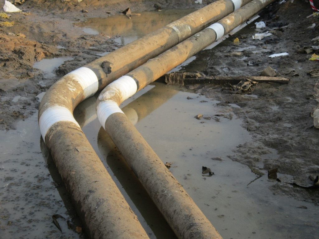
Figure 7: Installed Pipeline 3D Bends
4.2.5 Medium Used to Propel the Tool
There are pigging tools that can be used for both liquid and gas mediums. However, there is a specific tool which can only function efficiently in a medium. So the selection of the tool should take into consideration the fluid been transported or that will be utilised to propel the pig.
4.2.6 Pipeline Inline Components
Inline Components such as valves Tee’s are major factors that can affect the piggability of a pipeline. There are instances that wrong valves are installed on pipelines. All piggable pipeline valves shall be full bore however several reduced bore valves have been encountered during pigging operations. The implication is the pig will be trapped on the valve.
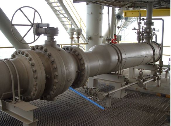
Figure 8: Piggable Pipeline Full Bore Valve
Also, all branch connection to a piggable pipeline using Tee’s shall be appropriately specified. Only barred Tee shall be utilised for piggable pipelines. However, the use of barred tee is limited to branch connection size which is a function of company and codes requirements.
Below table shows requirements for branch connection to a pipeline that may be adopted as per ExxonMobil GP-59-01-05 (Pigging Systems).

Table 1: Barred Branch Connection Requirement
5 Layout and components of a pipeline Pigging System
In this section, I will try to itemise and explain each component of a pigging system. The pictures below show the 3D view of a Pig Launcher and Receiver and the schematic of a Pig Trap. It should be noted that there might be variation in the configuration, a number of attached nozzles depending on the fluid transported and the design philosophy. Also, take note of the Kicker line location for Launcher, it is at the back close to the end closure while for a receiver it is at the front close to the reducer. This is one of the major difference between a Launcher and a Receiver.

Figure 9: 3D Model of a Gas Pig Receiver

Figure 10: 3D Model of a Gas Pig Launcher
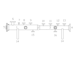
Figure 11: Generalized Schematic of a Pig Launcher
See below the names of each attachment to a pig Trap.
- Major Barrel
- Reducer
- Minor Barrel
- Nozzle Attachment to Pig Trap Valve
- End Closure or Door
- Kicker Line Nozzle Connection
- Pressure Indicator Nozzle Connection
- Major Barrel Vent Line Nozzle Connection
- Relief/Vent Line Nozzle Connection
- Pig Signaller Nozzle Connection
- Pressure Indicator Nozzle Connection
- Minor Barrel Relief/Vent Line Nozzle Connection
- Purge Line Nozzle Connection
- Pig Launcher Support
- Major Barrel Drain Nozzle Connection
- Minor Barrel Drain Nozzle Connection
- Equalization or Balance Line Nozzle Connections (Major Barrel)
- Equalization or Balance Line Nozzle Connection (Minor Barrel)
Following the numbering system above l will explain briefly each component and others that are not part of the above listed.
5.1 Major Barrel
The major barrel is a pipe with a diameter greater than the diameter of the minor barrel. It is usually bigger to facilitate easy loading of the pig into the launcher or easy unloading of the pig from the Pig Receiver. Selecting the major barrel size is critical to effective pigging operation. As per SHELL DEP 1.40.10.13-Gen pipelines of sizes smaller than NPS 20”: the major Barrel nominal diameter should be 50 mm (2 in) larger than the pipeline’s nominal diameter.
Also, the DEP requires that pipelines with nominal diameter DN 500 (NPS 20) and larger: the major barrel’s nominal diameter should be 100 mm (4 in) larger than the pipeline’s nominal Diameter
Also when specifying the major barrel size, the internal diameter of the barrel should be considered. When the barrel is made of low-grade pipe material this will result in a very thick barrel that may be close in internal diameter to the pipeline which can affect pipeline piggability.
5.2 Reducer
The reducer is the connection interface between the Pig trap major barrel and the minor barrel. The reducer is welded to the major and the minor barrel. For horizontal pig traps, eccentric reducers are recommended however concentric reducers may be used depending on client requirements. Concentric reducers are recommended for vertical pig launchers.
The dimensions of the reducers (concentric and eccentric) shall be obtained from ASME B 16.9 (Factory-Made Wrought Buttwelding Fittings) or other generally acceptable codes and standards.
5.3 Minor Barrel
This is the smaller diameter section of the pig trap. It usually has the same outside diameter as the pipeline.
The internal diameter of the minor barrel should be the same as that of the pipeline or minimal variation is permitted. When there is a significant difference between the internal diameter of the minor barrel and the pipeline, there is the possibility of the pig been unable to exit the barrel for launchers or enter the barrel for receivers.
SHELL DEP stipulates that transitions in the internal diameter of the barrel due to wall thickness variation greater than 2.4 mm shall be tapered to a maximum angle of 14o to the pipe axis to allow the smooth passage of a pig.
5.4 Nozzle Attachment to Pig Trap Valve
The nozzle is the last component downstream of the pig launcher or first component upstream of the pig receiver. It should be noted that instances when pig traps are welded to pipelines the nozzle, shall be eliminated from the drawing,
An isolation valve shall be installed at the transition from the pig trap to the pipeline. For flanged valves, the nozzle is the connecting element to the valve. The nozzle shall be appropriately rated to the design pressure and temperature. Nozzle dimensions may be obtained from ASME B16.5 (Pipe Flanges and Flanged Fittings NPS 1/2 Through NPS 24), ASME B16.47 (Large Diameter
Steel Flanges NPS 26 through NPS 60 Metric/Inch Standard) or other applicable codes and standards
5.5 End Closure or Door
The end closure or door is the only access to feed the pigging tool into the launcher or retrieved retrieve the pigging tool from the receiver. The end closure shall be welded to the major barrel. The end closure is the most critical part of the pig launcher because if the closure opens during pigging operation it can result in a serious accident. The end closure is usually made of a material that is compatible with the barrel. End closure is generally of quick opening type with an inbuilt safety interlock system to prevent the door/closure from opening during pigging operation. There are different types of closures with some suitable for vertical pig traps while others are suitable for horizontal pig traps. The end closure is mostly equipped with hinge assembly for horizontal installation and davit for vertical installations.
As stated in section 404,7 of ASME B31.4, Quick opening closures shall be equipped with safety locking devices in compliance with Section VIII, Division 1 UG-35(b) of the ASME Boiler and Pressure Vessel Code, however, closures can be designed to other codes and standards including PD 5500 / EN 13445

Figure 12: Hinged Type End Closure
5.6 Kicker Line
The kicker line connects the major barrel to the bypass line. The kicker line allows for fluid diversion from the bypass line to the barrel to launch the pig or allows for fluid diversion to receive the pig on the receiver. It should be noted that the kicker line position on a launcher barrel is at the back close to the end closure while for the receiver the kicker line is at the front of the major barrel close to the reducer

Figure 13: Kicker Line Location for Launcher

Figure 14: Kicker Line Location for Receivers
5.7 Pressure Indicators
Pressure indicators are a key component of a pigging system. All pressure gauges should be properly calibrated before commencing pigging operation. There may be a pressure indicator mounted on the major barrel and minor barrel, however, there are instances that one pressure indicator is used. With the indicator properly installed operator can check if the barrels are pressurised during pigging operations.
5.8 Vents/Relief Lines
Vent/Relief lines are critical components during pigging operation. They act as safety devices during pigging operation. The vent valve is manually open prior to the commencement of pigging operation
The Relief valves will open if the pressure in the barrel exceeds a set point. There is usually one of these valves installed on the major and minor barrel respectively.

Figure 15: Relief Lines
5.9 Pig Signallers
Pig signallers are alert devices installed on the minor barrel, on or before the minor barrel. They indicate the passage of a pig. They may also be installed at appropriate locations along the pipeline. When a pig is launched the barrel end closure is usually close so there is no way to know that the pig has left the barrel without the installation of a signaller. For launchers in most cases, there is one installed on the minor barrel and another installed downstream of the pig trap valve. The passage of the pig will generate a signal. Also without a pig signaller, it will be difficult to detect if the pig has arrived at the receiver this implies that it is mandatory to install at least one pig signaller on the receiver minor barrel, and or upstream of the receiver valve. There are two types of pig signallers: Intrusive and the non-intrusive type. The intrusive type is a mechanical device which requires that a hole should be bored on the pipeline and a flange or nipple connection installed. The Pig Sig is then installed on this connection.
Unlike intrusive type pig signallers, non-intrusive can be quickly installed and removed from the pipeline. They are strap-on devices and are equipped with sensors. The non-intrusive pig sig can detect the location of the pig as it approaches. They do not require boring a hole on the pipeline. The passage of a pig is indicated with colour light flashes.
5.10 Purge Lines
This is a small line equipped with valves (Check and an isolation valve) and blind connection for the introduction of inert gas into the barrel. They are used when the pig is not in operation.
5.11 Pig Trap Supports
The supports are the load-carrying member of the trap. They carry the dead weight of the trap when they are not in use and carry both live load and operational loads when in use.
Horizontal pig traps are supported on saddles usually two while vertical pig traps are supported on trunnion resting on the offshore platform framework.
5.12 Drain Lines
Like the name, these lines are used for draining liquid content from the pig trap. There is usually one drain line connected to the minor barrel and another connected to the major barrel. These two lines can be commingled into one line and routed to a closed drain system
5.13 Equalization or Balance Line
An equalization line connects the major barrel to the minor barrel. The equalization line is used to create equal pressure upstream and downstream of the pigging tool when it’s in the pig trap.
For launchers, a balanced line shall be provided to enable filling and pressurising of the barrel on both sides of the pig while for receivers a balanced line shall be provided to prevent any possible pressure differential across a received pig

Figure 16: Pressure Equalization Line on a Pig Launcher
5.14 Bypass Line
The bypass line is the major service line that connects the pipeline to the upstream or downstream facilities such as tank farm, compressor station, pump station, reception facilities etc. This branch line connection to the pipeline is usually located downstream of the big launcher valve or upstream of the pig receiver valve. The kicker line takes its source of fluid from the bypass line.

Figure 17: Bypass Line
5.15 Valves
There are no piping networks without installed valves however when it comes to pigging system design valves type selection must be carefully performed. There are various valves installed in the pigging system however I will explain briefly some requirements for consideration.
5.15.1 Pig Trap Valve
The pig trap valve provides isolation of the pig trap from the pipeline system when it is not in use. It is imperative that the valve is in good working condition. Some client requires that a double block and bleed valve should be installed to achieve this isolation
The pig trap valve(s) shall be a full-bore, tight shut-off ball valve or through-conduit gate valve to permit the easy passage of pigs.
Also, the minimum internal diameter of the valves shall be consistent with that of the pipeline.
5.15.2 Bypass Valve
This valve is located close to the branch tee connection to the pipeline. The valve is installed to isolate the pipeline from facilities connected to the pipeline. Any of the following valves can be installed as a bypass valve: tight shut-off ball valve, pressure-balanced plug valve or through-conduit gate valve
5.15.3 Kicker Valve
This is the valve installed on the kicker line. The gradual opening of this valve bypasses fluid flow from the bypass line to the barrel. This valve should be installed as close as possible to the bypass line.
A tight shut-off ball valve, pressure-balanced plug valve or through-conduit gate valve may be installed for this purpose to isolate the bypass line from the barrel.
5.15.4 Drain Valves
These are mostly manually operated valves. The opening of these valves permits the draining of liquid content from the pig trap. Tight shut-off quarter-turn ball or pressure balanced plug valves can be used for this purpose. When debris is expected the use of ball valve and gate valve should be carefully evaluated.
5.15.5 Vent Valves
These valves are installed on the vent lines. They are used to manually depressurise the pig traps. Tight shut-off ball valves, gate valves or plug valves can be used. For gas lines, a globe valve is very suitable for these applications.
5.16 Pig Drip Tray or Drip Pan
Drip tray shall be provided under the end closure permanently or temporarily. The tray maybe is provided with appropriate piping to a closed drain system if a high volume of liquid is anticipated. Vertical launcher installed on the offshore platform usually has the tray installed concentrically or eccentrically around the barrel. When the end closure is open especially for liquid pipelines there is the possibility of liquid draining out. The tray is used to collect the liquid for onward transport to the drain system.
5.17 Lifting System/ Davit
This is required especially when the pigging operation involves the use of intelligent pigs. These pigs are heavy and cannot be easily lifted. In most cases, a Davit of appropriate rated capacity is installed to facilitate the lifting of the pigging tool.
5.18 Pig Trays.
A Pig Tray is the mechanical equipment that facilitates easy loading of the pig into the Launcher or easy unloading of the pig from the receiver. The height of the tray should be design such that it aligns with the bore of the major barrel. Hand, Davit or any other mechanical device may be used to push the pig into the barrel.
Sometimes the trays may be incorporated into a Trolley that can be used to convey the pigging.
Pig trays are not applicable to vertical launchers and receivers, a means of transporting the pigging tool is the only requirement.

Figure 18: Pig Trolley with Installed Tray
6 References
ASME B16.5: Pipe Flanges and Flanged Fittings NPS 1/2 through NPS 24
ASME B16.47: Large Diameter Steel Flanges NPS 26 through NPS 60 Metric/Inch Standard
ASME B 16.9: Factory-Made Wrought Buttwelding Fittings
ASME B31.4: Pipeline Transportation Systems for Liquid Hydrocarbons and Other Liquids
ASME B31.8: Gas Transmission and Distribution Piping Systems
SHEEL DEP 31.40.10.13-Gen: DESIGN OF PIPELINE PIG TRAP SYSTEMS
ExxonMobil GP 59-01-05: Pigging Systems

 To all knowledge