1 Overview of the Article
Pipelines design and construction entails series of technical activities that must be adequately planned, including executing pipeline road and railroad crossings. This article will focus on pipeline crossings (roads and railroads). However, more emphasis will be laid on road crossings.
Pipeline crossing roads or railway lines are subjected to more external loads compared to those buried underground. These external loads subject the installed pipeline at the crossing location to higher stresses. If the stresses exceed certain limits, the pipeline may fail at this location.
It is, therefore, imperative to design the pipeline against the effects of these external loads.
Various techniques have been developed for these analyses, including those proposed by the American Society of Civil Engineers (ASCE) and the American Petroleum Institute (API).
This article covers pipeline crossing analysis for roads and railways. The pipelines described in this article are steel pipelines conveying liquid or gaseous hydrocarbons.
The principles described in this article are as per API 1102, and writers experienced acquired in executing road and railway crossings.
During construction, the pipeline may cross railroads and roads. Therefore, it is crucial to implement a crossing methodology that will have minimum impact on traffic, minimal cost, etc.
Some of the techniques for crossing roads and railroads will be described in this article.
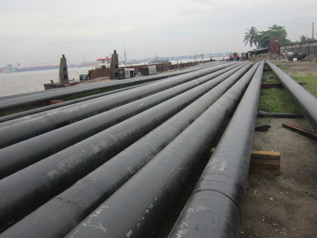
Figure 1: Pipeline Construction
2 Introduction
Pipelines are the most economical and efficient means of transporting hydrocarbon fluids (liquid and gasses). In many cases, pipelines travel a hundred to over a thousand kilometres from their start point to their endpoint.
Pipelines are installed on acquired Right of Way (ROW). However, the acquired ROW may intersect and cross various features and third party facilities, including rivers, railway lines, roads, third party pipelines, electric cables, and drainages. Any of the above features are categorised as obstacles that must be critically considered in the pipeline’s design.
This article will focus on two of the major obstacles: roads and railroads.
A typical pipeline spanning 100km may encounter over twenty roads; however, the number of railway lines encountered may be predominantly smaller than the roads depending on the pipeline location and the routing.
There are various types of roads; the classification of roads may vary from one country to another. This article’s focus is not on the types of roads; however, some classifications are briefly discussed because they are a key input to pipeline road crossing design.
Foot Paths: these are predominantly pathways used by villagers, connecting small settlements or residential areas.
Single Carriage Way: A single carriageway or undivided highway is a road with no reservation or boundary to separate cars moving in opposite traffic. These roads may have one, two, or more lanes.
Dual Carriageways: Dual carriageways or divided highways are roads that have carriageways in place for cars moving in opposite directions, i.e. they have a central reservation or boundary to separate cars moving in the opposite direction
The essential characteristics of roads for pipeline road crossing design are the traffic volume the roads handle and the road’s width, referred to as the crossing length.
There are various types of railway lines that are defined in terms of rail gauge. The gauge of a rail is the minimum perpendicular distance between the inner faces of the two rails.
There are various types of Rail Gauges, including broad gauge, standard gauge, meter gauge, and narrow gauge. The most crucial factor to consider in pipeline railway line crossing is the railway’s width, the number of parallel railway lines that result in the total crossing length. A combination of all the rail tracks and road carriageways contributes to the load transferred to the pipeline.
2.1 Pipeline Road Classification
In Pipeline design, the road classification should be set out as per the project design philosophy; however, roads are mainly classified as
2.1.1 Major roads
These are roads of very high importance. They may be single carriageway or dual carriageway. They are roads that handle a high volume of traffic. Therefore any activity that will result in traffic obstruction should be avoided.
2.1.2 Minor Roads
These are roads with low traffic volume. They are mostly single lane. Depending on government regulation, traffic obstruction and diversion may be permitted.
2.1.3 Foot Paths
These are not major or minor roads. In most cases, they are created out of the necessity to link settlements or communities.
2.2 Classification of Railroads
There is no measure classification for railroads. However, a simple classification may be developed to group the railroads. They may be grouped by the number of parallel tracks.
2.3 Documentation of the Crossing Obstacles
After all the roads and railroads have been identified in the pipeline route, they should be adequately documented in a spreadsheet. This document is termed the crossing list, and it may also contain other crossings such as river crossing, pipeline crossing, etc.
Information such as crossing length, type of road, road classification, and crossing technique should be included in the developed spreadsheet. The design of each of the roads and the railroad is performed. A detailed crossing drawing shall be prepared for all the major roads and railroads. Typical drawing may be utilised for all minor roads and footpaths.
Also, permits to cross each of the roads and railway track should be obtained accordingly before execution of the crossing during construction.
2.4 Permitting from Appropriate Authority
Before the execution of road and railroad crossing, all applicable permits must be obtained from various organs of government. Unions such as road transport operators should also be informed if the crossing methodology will entail shutting down the road.
If necessary, the ministry in charge of the road should have its personnel onsite during the construction activities because they will give a final certification that the crossing was executed as per the set guidelines.
It should also be noted that some of the ministries (ministry for roads and railways) have guidelines that govern pipeline crossings. Therefore these guidelines shall be obtained during design. The design and the construction shall be executed to satisfy these guidelines.
3 Roads and Railroads crossing techniques
There are various techniques used for executing road or railroad crossing. Some of the most common crossing techniques include Open cut (Trenched Crossing), horizontal directional drilling, microtunnelling/ pipe jacking, auger boring/Pipe Jacking, pull back technique. In the subsections below, we will discuss the most popular crossing techniques.
3.1 Open Cut Technique
This technique is majorly employed for road crossings. Open crossings are rarely used for executing railroad crossing.
This is a type of crossing technique that entails excavating a pipeline trench across the road. The pipeline is installed, and the road reinstated to its original state or better status. The road involved may be totally or partially closed during the pipeline installation. This crossing methodology is utilised for footpaths and, in some cases, minor roads. Before open cut is performed, all permits are obtained from government authorities, and appropriate union informed of the road closure. Also, alternative routes should be made available and diversions marked during the road closure.
If the road is wide enough, one section of the road may be closed while the pipeline installation is ongoing on the other road section. Traffic is diverted to a section of the road as work is ongoing on the other section. After the first section, the road may be backfilled or a temporary ramp installed across the trench before traffic is diverted back to the backfilled section. This method requires appropriate planning and traffic control for the smooth execution of pipeline installation.
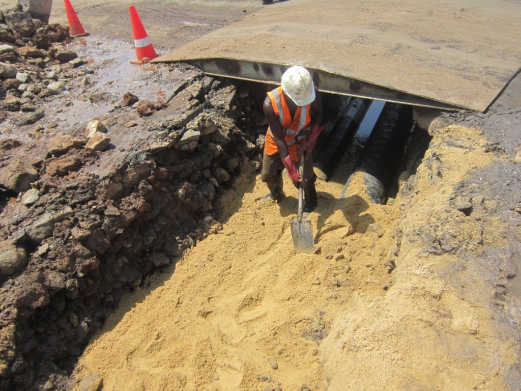
Figure 2: Ramp Installed at Pipeline Road Crossing
3.2 Trenchless or Closed Crossing Methodology
This is the most common technique adopted for highways and railroads crossing.
This method entails installing the pipeline under the road or railroad without traffic disruption. This method is more expensive than the open crossing methodology. However, it is less expensive compared to horizontal directional drilling.
There are various trenchless technologies; selection criteria include the complexity of the crossing, the crossing length, and the soil characteristics.
Below are some of the trenchless crossing techniques.
3.2.1 Auger Boring with Pipe Jacking
This technique is utilised for short length or medium crossing length. It is one of the most popular techniques. All major roads could be crossed utilising auger boring. If the crossing length cannot be executed at once, the crossing may be broken down into sections with all sections intersecting at an appropriate location.
This technique requires the excavation of pits on either side of the road or railroad to be crossed.
The excavated pits’ depth is a function of the minimum cover depth required for the pipeline, the drilling machine’s height, etc. Sheet piling, in combination with dewatering, may be required during the pipeline installation. The sheet piles prevent the pits from collapse, especially where the soil is not stable.
One of the two pits is used as the pipeline launch pit, while the other is the pipeline reception pit. The reception pit is usually smaller than the launch pit. The launch pit length should accommodate at least one spool length of pipe, the auger boring machine assembly, and appropriate space required for other activities’ operation and performance. Additional space is also required on both sides beside the pits to accommodate the pits’ excavated material and the bored hole.
Note in establishing the depth of the launch pit, the height of the auger boring machine and the auger machine rail height should be properly evaluated to ensure the minimum pipeline cover is met.
After the pit has been excavated and prepared, the auger boring machine is lowered into the pit. The machine runs on a rail line such that it can move forward and backwards on the rail. The machine is equipped with a power unit that transmits rotating power to the auger boring system. The power unit is directly behind the auger boring system.
Before the commencement of boring, the auger boring machine is retracted backwards to accommodate a pipe spool. The pipe spool is inserted into the space between the auger boring machine and the soil entry point. An auger drill is inserted into the pipe, and a “cutting head” is fixed to the front of the auger drill pipe. Note that the auger drill has a helical cutting tool across its entire length. The helical cutting aids in the transportation of the cut soil backward through the pipe.
After completing the setup, the power system is turned on, and the auger boring machine begins to rotate. The cutting head is gradually driven into the soil to commence the drilling operation. Note the cutting head might be slightly larger in diameter than the pipeline outside diameter to create clearance for the pipe. The pipe spool should be horizontal and should be appropriately supported during drilling. After installing the first spool, the machine is retracted, and another spool is welded to the first pipe. The second spool should have the auger drill inserted and connected to the first pipe auger drill. The process continues until the pipe and the cutting head appears at the reception pit. The machine is turned off, the cutting head and auger drill removed from the installed pipe.
The pipe installed by this method may be the carrier pipe or casing pipe, depending on the project requirement.
Note most of the excavated materials are transported through the inside of the pipe via the spiral rotation of the auger drill.
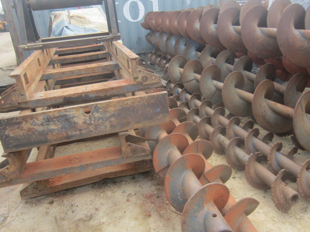
Figure 3: Auger Drill Pipe and Rail Track of an Auger Boring Machine
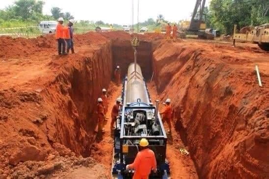
Table 1: Pipeline Installation Utilising Auger Boring Technique
3.2.2 Pull Back Methodology
This boring technique is commonly used for short crossing length.
This technique utilises two pits on either side of the road/railroad. The launch pit may not be as long as that utilised for auger boring. The reception pit length should be long enough to accommodate at least one spool length of pipe. Also, there should be available clearance for welding activities performed during pipeline pullback if required.
Just like the auger boring, the launch and reception pits are excavated. If required sheet piles should be used to shore the sides of the pits to provide stability.
The boring machine is lowered into the launch pit. The height of the machine should be taken into consideration in determining the depth of the pits.
The machine can move forward and backwards on a rail track.
This setup utilises drill pipes and a drill head that should bore a hole diameter greater than the pipeline’s external diameter.
Before the commencement of drilling activities, the drill assembly is driven to the back of the rail track, a drill pipe is connected to the rotating mechanism, and a drill head is connected to the front of the drill pipe.
The machine is turned on, and the rotating motion drives the drill head into the soil. The rotating assembly is disconnected from the first drill pipe, and subsequent drill pipes added until the drill head appears at the reception pit. The machine is turned off, and preparation for the pullback is performed.
A pulling head is welded to the first pipe to be pulled into the hole. This head is connected to the head of the boring machine at the reception pit. The machine is turned on and gradually retracted backwards until the first pipe is pulled into the hole. A second pipe is welded to the first and pulled back into the hole until the pipe appears at the launch pit.
Note the pipe should be appropriately supported on rollers at the reception pit to facilitate easy pullback.
The machine is disconnected after the pullback is completed.
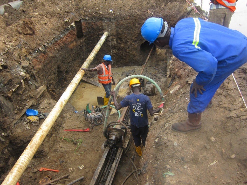
Figure 4: Drilling Operation for Pipe Pullback
3.3 Horizontal Directional Drilling
Horizontal directional drilling (HDD) is a technique that can be utilised for road or rail crossing without traffic disruption during pipeline installation. This method does not require the excavation of pits on either side of the crossing. However, a huge amount of land is required for pipeline welding and installation of the drill rig. The land required for installation activities may not be acquired but leased from third parties.
HDD can be utilised for crossing length exceeding 1000m. Therefore, considerable crossing length can be conveniently executed using this methodology.
HDD is mostly utilised for considerable crossing lengths such as high ways with many carriageways, locations with multiple parallel rail lines, unstable locations where other trenchless techniques cannot be deployed, etc.
The pipeline is not installed horizontally straight. It takes a curve shape utilising the pipe flexibility. Note pipeline bends are not utilised.
The curved radius of the pipeline must not be lesser than the pipeline’s minimum elastic bending radius.
A drill rig is set up on one side of the obstacle, and the entire pipeline length to be installed across the obstacle is welded at the other side of the obstacle. All quality-related activities are performed on the pipeline above ground before it is installed.
A hole is drilled under the obstacle from the entry point to the exit point. Note the drill length is achieved by continuously adding drill pipes to the drill setup. There are various drilling stages: the pilot drill and a series of reaming until the desired hole diameter is achieved.
After drilling is completed, the welded pipeline is connected to the drill bit/pipe assembly and pulled back into the hole until the pipeline appears at the drilling start point (Entry Point).
If you require more details on horizontal directional drilling, refer to our article: HORIZONTAL DIRECTIONAL DRILLING (https://epcmholdings.com/horizontal-directional-drilling/)
Some of the advantages of utilising HDD for crossing includes:
- The pipeline can be installed at greater depths across the obstacles compared to other crossing technology.
- In locations where the water table is very high, other crossing techniques might be challenging to utilise. However, the HDD rig can be set up at an appropriate stable location where the crossing can be executed.
- The entire crossing length is executed at once without breaking it into sections, as may be the case in some other trenchless technique.
HDD is a high-level technology and must be appropriately planned and executed by a certified organisation and qualified personnel.
It is costly compared to other crossing techniques. Therefore, there must be a justification before deploying this technique.
Because HDD utilises the pipeline flexibility, the entry and exit point must be appropriately calculated. For small crossings and large diameter pipelines, this is difficult if the pipeline route is not appropriately designed.

Figure 5: Horizontal Directional Drilling
4 Pipeline Crossing requirements
Some of the requirements for pipeline crossing roads and railroads are presented in the subsections below. Requirements are based on the recommendations on API 1102.
Carrier pipe
As per section 2.3.1 of API 1102, a carrier pipe is a steel pipe for transporting gas or liquids.
Cased Pipeline
A cased pipeline is a pipeline (Carrier pipe) installed inside a casing that crosses beneath a road or railroad.
Uncased Pipeline
An uncased pipeline is a pipeline installed beneath a road or railway line without a casing. Below are some of the design requirements for an uncased pipeline crossing road.
4.1 Uncased crossing
When pipelines crossing roads or railroads are uncased, the stresses resulting from the external loads are transferred directly to the pipeline. These stresses must be carefully evaluated compared to allowable values stipulated in codes and standards such as API 1102. Pipelines are uncased because it is more challenging to protect cased pipelines against corrosion.
The requirements in the subsections below are as per the recommendation of API 1102
4.1.1 Road Crossing
4.1.1.1 Crossing Angle
The crossing angle, which is the intersection between the pipeline and the road, is defined in section 4.3.1 of API 1102. This angle should be near to 90 degrees, and in no case should it be less than 30 degrees
4.1.1.2 Crossing Location
Crossing in wet terrain and rocky terrain should be avoided as much as possible. It is difficult to bore through rocky soil while it is difficult to excavate a pit for the boring machine in wet terrain.
4.1.1.3 Burial Depth (Cover Requirement)
The minimum burial depth recommended for uncased pipeline crossing roads is stated in section 4.4.2.
The pipeline cover is measured from the top of the pipeline to the surface of the road.
The data below and images are obtained from API 1102.

Figure 6: Highway Crossing

Table 2: Cover Requirement for Uncased Pipeline Crossing Roads
4.1.2 Railroad Crossing
4.1.2.1 Crossing Angle
The crossing angle is the angle of intersection between the pipeline and the railroad. Its requirement is defined in section 4.3.1 of API 1102. This angle should be near to 90 degrees and shall not be lesser than 30 degrees
4.1.2.2 Crossing Location
Crossing location should be selected such that wet and rocky terrain are avoided. It is difficult to bore through rocky soil while it is difficult to excavate the launch and the reception pits in wet terrain.
4.1.2.3 Burial Depth (Cover Requirement)
The minimum recommended cover for uncased pipeline crossing railroads are stated in section 4.4.1.
The pipeline cover should be measured from the top of the pipeline to the base of the rail.
The data below data and image are obtained from API 1102.
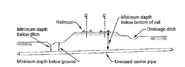
Figure 7: Railroad Crossing

Table 4: Cover Requirement for Uncased Pipeline Crossing Railroads
4.2 Cased Crossing
When casing pipes are used, the stresses are not transferred to the carrier pipe; the casing pipe takes the external load. There is a minimum recommended thickness for casing pipes. Casing pipes with wall thickness lesser than these recommended values may fail when they are loaded beyond certain limits.
When a casing pipe is used, the carrier pipe should be designed to meet the applicable code requirement for transporting the fluid, such as ASME B31.4, ASME B31.8.
Cased pipeline crossing is not as popular as uncased crossing due to possible increased corrosion emanating from the cased section. After the casing pipe has been successfully installed, the carrier pipe is installed inside the casing pipe. The carrier pipe should be supported circumferentially around the casing pipe by installing insulating spacers along the pipeline’s length.
The below requirements for cased crossing are drawn from API 1102
4.2.1 General requirement
I have grouped some of the requirements, including installation requirements, under general requirements. It should be noted that there are other requirements not stated in this article; refer to API 1102 and other publications for further information’s:
When a casing pipe is installed using a trenchless technique, the overbore between the pipe and the soil should be minimal to minimise the void between the pipe and the adjacent soil. A large overbore may eventually lead to the collapse of the surrounding soil, which may transfer shock loads to the casing pipe.
All the casing pipes should be wholly joined. The welding should be complete and be performed by qualified welders.
Multiple carrier pipes can be installed in one casing pipe, but each carrier pipe should be appropriately supported and insulated from the others.
There shall be no internal obstructions in the casing pipe to facilitate easy installation of the carrier pipe.
The casing pipe should be straight. The bedding for casing pipe installed using open cut should be uniform, backfill and padding material should be such that damage to the pipeline and casing pipe coating is prevented.
The carrier pipe should be appropriately supported circumferentially by insulating materials supported on the casing pipe. The insulators should be appropriately spaced.
The casing pipe should be tested to verify if it is electrically isolated from the carrier pipe.
Casing seals shall be installed at both ends of the casing pipe. The seals prevent water intrusion from the surrounding soil into the casing pipe. The water intrusion speeds up the corrosion of the pipeline.
4.2.2 Casing Material
Casing pipes are made from steel materials, including used or new pipes rejected mill pipes. The casing may be longitudinally split pipes that are further welded together.
4.2.3 Casing Pipe Size
The casing pipe internal diameter should be large enough to facilitate easy installation of the carrier pipe. Size should be such that the external loads are not transferred to the carrier pipe. As stated in section 5.3 of API 1102, the casing pipe should be at least two (2) nominal pipe size larger than the carrier pipe. This implies that if the carrier pipe is NPS 10, the casing pipe should be at least NPS 14.
4.2.4 Pipeline Location and Alignment
Cased pipeline should be installed at an intersecting angle close to 90 degrees to the road or railroad; in no instance should the angle be lesser than 30 degrees.
For road crossings, the pipeline casing should extend a minimum of 2 ft. (0.6 m) beyond the toe of slope or base grade, or 3 ft. (0.9 m) beyond the bottom of the drainage ditch, whichever is greater.
For rail crossings, the casing pipe should extend at least 25 ft. (7.6 m) to each side from the centreline of the outside track or 45 ft. (13.7 m) from the centreline of the outside track when the casing pipe is open at both ends.
4.2.5 Casing Vent
A casing vent shall be installed on the casing pipe. One or two may be welded to the casing pipe. The minimum projecting height of casing pipe shall be 4 ft. (1.2 m) above the ground surface as stipulated in section 5.10.5 of API 1102
4.2.6 Recommended Casing Pipe Thickness
When a casing pipe is installed using a trenchless technique, the minimum recommended thickness is stated in Annex C of API 1102. Casing pipe for railroad crossing may vary in thickness depending on if the pipe is coated/cathodically protected or not
The table below is an extract from API 1102 Annex C
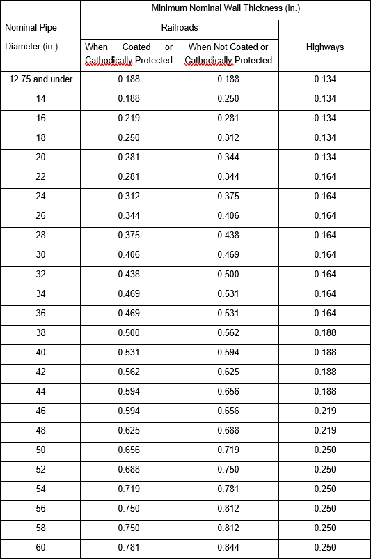
Table 5: Minimum Nominal Wall Thickness for Flexible Casing in Bored Crossing
Casing Pipes installed by an open cut or trenched crossing, the thickness stated in Table 5 above can be used if the cover depths stated in Table 6 and 7 are met. If the cover depth requirement is not satisfied, the casing pipe’s wall thickness should be increased, or stabilised backfilled should be used at the pipeline crossing.
4.2.7 Cased Pipeline Cover requirement – Road Crossing
The recommended cover depth stated in table 6 is extracted from API 1102. Note the cover depth should be measured from the top of the pipe to the surface of the road (highway)

Table 6: Cover Requirement for Cased Pipeline Crossing Roads
4.2.8 Cased Pipeline Cover requirement – Railroad Crossing
The minimum casing pipe cover depth measured from the top of the casing pipe to the rail base is stated in section 5.7.1 of API 1102. See below values extracted from API 1102.
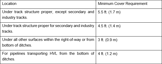
Table 7: Cover Requirement for Cased Pipeline Crossing Railroads
5 Uncased Pipeline Crossing design
The focus of this section is to perform an uncased pipeline road crossing design. Kindly note that some of the definitions and explanations are tailored to road crossings. However, they may also apply to railroad crossings.
The procedure for checking the stresses in the pipeline at crossings is shown in Figure 2: section 4.6.12 of API 1102. Design
As previously stated, uncased pipelines are subjected to both internal and external loads.
The internal loads result from the internal pipeline pressure, while the external loads result from dead loads (earth loads, i.e. weight of soil cover) and live loads (road or railroad traffic loads). An impact factor should be applied to live loads.
5.1 Stresses Due to Internal loads
5.1.1 Circumferential Stress Due to Internal Pressure.
This stress is evaluated using equation 7 in API 1102
![]()
Where
P = Internal Pressure or MAOP/MOP (Psi or kPa)
D = Pipeline Outside Diameter
t = Pipeline Wall thickness
5.2 Stress Due to External Loads
5.2.1 Stresses Due to Earth Load
The circumferential stress resulting from earth load is evaluated using the equation below.
![]()
Where
KHe = Stiffness factor for circumferential stress from earth load
Be = Burial factor for earth load
Ee = Excavation factor for earth load
Ps = Soil unit weight (lb/in3 or kN/m3) mostly taken as 120lb/ft3 for most soil
D = pipe outside diameter (in. or m)
KHe (stiffness factor) is used to account for the interaction between the soil and the pipe. This is a function of the pipe wall thickness ratio to the pipe’s diameter (tw/D) and modulus of soil reaction. The values of KHe can be obtained from the graph shown in Figure 3 of API 1102. The graph shows values of E’ as a function of (tw/D). E’ values for auger boring installation are from 0.2 to 2.0kips/in2; however, a value of 0.5kips/in2 is mostly used.
Below graph for obtaining KHe is extracted from API 1102
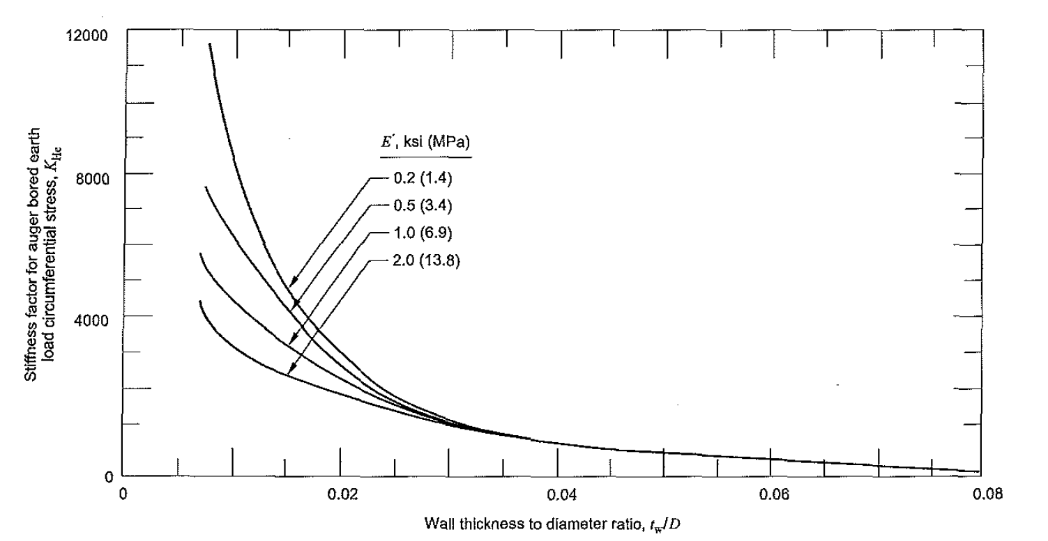
Figure 8: Stiffness Factor for Earth Load Circumferential Stress (KHe)
Burial factor (Be)
The burial factor is obtained as a function of the pipe cover ratio (depth) to the bore diameter (H/Bd). This value can be obtained from Figure 4 of API 1102
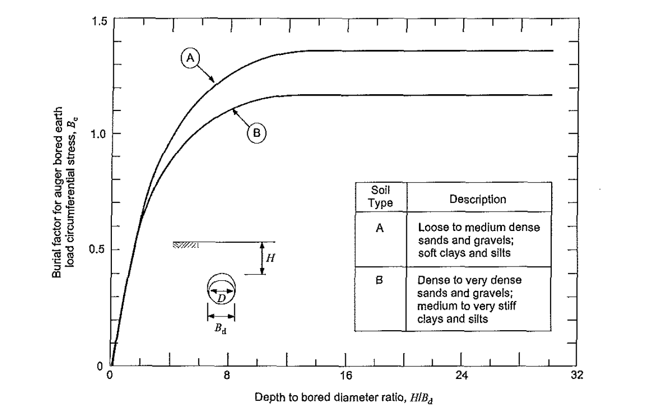
Figure 9: Burial Factor for Earth Load Circumferential Stress (Be)
Unknown bored diameter can be taken as Bd = D+2in
For open cut Bored Diameter Bd = D
Where D = pipeline outside diameter
Excavation Factor (Ee) is a function of the bore diameter ratio to the pipeline diameter.
This value can be obtained from Figure 5 of API 1102
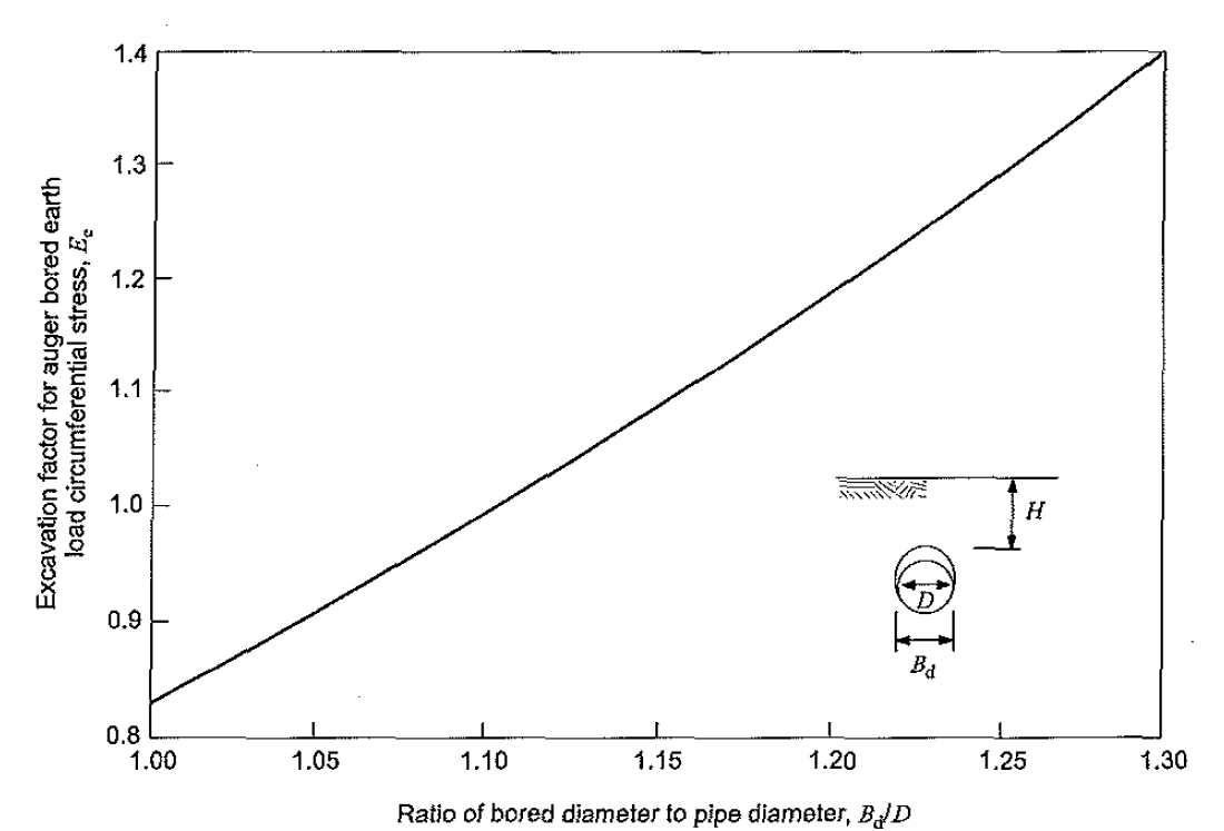
Figure 10: Excavation Factor for Earth Load Circumferential Stress (Ee)
5.2.2 Stresses Due to Live Loads
5.2.2.1 Surface live Loads
The highway live loads (w) results from the road surface wheel loads. Only the load of one of the wheel sets is considered in the crossing design. The design wheel load is taken as either the truck single axle load (Ps) or the maximum wheel load from a truck tandem axle set (Pt). Refer to section 4.7.2.2.1 of API 1102 for details of how to convert truck’s axle loads into equivalent wheel load
The recommended maximum single axle wheel load (Ps) = 12kips (53.4kN)
The recommended maximum tandem axle wheel load (Pt) = 10kips (44.5kN)
Selecting single or tandem axle loading for crossing design depends on the pipeline diameter (D), cover depth (H), and the road surface type (flexible pavement, rigid pavement or no pavement). The critical axle configuration for various pavement types, cover depth and pipe diameter are given in Table 1 of API 1102. See table below.
Based on the Ps and Pt, the applied design surface pressure can be evaluated.

Where P = Pt or Ps (lbs or kN)
Ap = the contact area over which the wheel load is applied. Ap is taken as 144in2 (0.093m2)
Substituting (P) and (Ap) into the equation to obtain (w)
This implies that for
Single Axle Loading w = 83.3psi (574kPa)
Tandem axle Loading w = 69.4psi (479kPa)
For other wheel loads, refer to Annex A. of API 1102
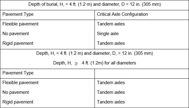
Table 12: Critical Axle Configurations for Design Wheel Loads of Ps = 12 Kips (53.4kN) and Pt = 10 Kips (44.5kN)
5.2.2.2 Impact Factor
It is recommended to increase the live loads by an impact factor (Fi). The impact factor is a function of pipeline cover at the crossing location. Impact factors are shown in Figure 7 of API 1102. Below is an extract from API 1102.
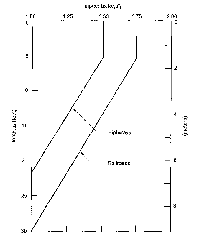
Figure 11: Recommended Impact Factor Vs Depth
5.2.2.3 Highway Cyclic Stresses
5.2.2.3.1 Cyclic Circumferential Stresses Due to Highway Vehicular Load (Psi or KPa)
This is calculated using the equation below
![]()
Where
KHh = Highway stiffness factor for cyclic circumferential stress
GHh = Highway geometry factor for cyclic circumferential stress
R = Highway Pavement type factor
L = Highway axle configuration factor
Fi = Impact factor.
W = applied design surface pressure (psi or kPa)
The highway stiffness factor (KHh) is a function of the pipeline wall thickness ratio to the diameter. The values are presented in the graph in 14 of API 1102.
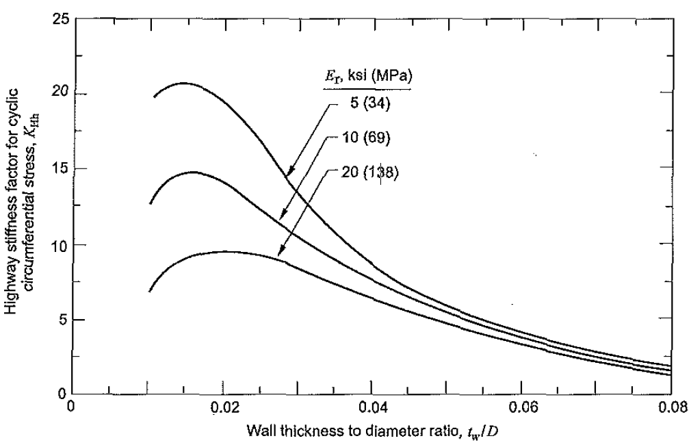
Figure 12: Highway Stiffness Factor for Cyclic Circumferential Stress, (KHh)
The Highway geometry factor is presented in Figure 15 of API 1102
Axle configuration factor (L) and highway pavement factor ® are dependent on the cover depth (H), pipeline diameter (D) and the axle configurations. Values of R and L are extracted from Table 2 of API 1102, as shown below.
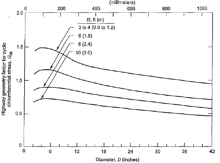
Figure 13: Highway Geometry Factor for Cyclic Circumferential Stress, GHh
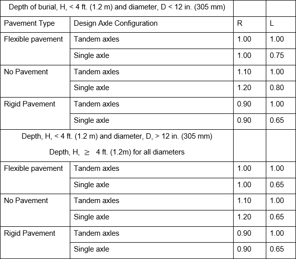
Table 12: Highway Pavement Type Factors, R, and Axle Configuration Factors, L
5.2.2.3.2 Cyclic Longitudinal Stresses Due to Highway Vehicular Load
This is calculated using the equation below.
![]()
Where
KLh = Highway stiffness factor for cyclic longitudinal stress
GLh = Highway geometry factor for cyclic longitudinal stress
R = Highway Pavement type factor
L = Highway axle configuration factor
Fi = Impact factor.
W = applied design surface pressure (psi or kPa)
See figure 16 and 17 of API 1102 for graphs showing values of KLh and GLh, respectively.
5.2.3 Allowable Stresses
5.2.3.1 Allowable Circumferential Stress
The circumferential stress is calculated using Barlow equation below.
![]()
The maximum allowable circumferential stress is
![]()
Where
P = internal pressure, taken as the MAOP or MOP (psi or kPa)
D = Pipeline outside Diameter (in. or mm)
t = Wall thickness of the pipeline
F = Pipeline design factor see ASME B31.4 and 31. 8 for values
E = Longitudinal joint factor
T = Temperature derating factor
SMYS = Pipeline specified minimum yield strength
5.2.3.2 Total Effective Stress Check
The total effective stress (Seff) is calculated using the equation below.

Where
Esteel = Steel young’s modulus of elasticity
S1 = Maximum circumferential stress
S2 = Maximum Longitudinal stress
S3 = Maximum radial stress
5.2.3.3 Check for Fatigue
The essence of this check is to compare the stress on components normal to a weld against the allowable limits stated in API 1102, referred to as fatigue endurance limit.
5.2.3.3.1 Girth Weld –Cyclic Longitudinal Stress Check
For highways, the fatigue check is performed using equation 17 of API 1102
![]()
5.2.3.3.2 Longitudinal Weld –Cyclic Circumferential Stress Check
For highways, the fatigue check is performed using equation 17 of API 1102
![]()
Where
SFG = Fatigue endurance limit of girth weld = 12,000 psi (82,740 kPa). See Table 3 API 1102
SFL = Fatigue endurance limit of the longitudinal weld (psi or kPa) obtained from Table 3 API 1102
F = Pipeline design factor
5.3 Worked Example
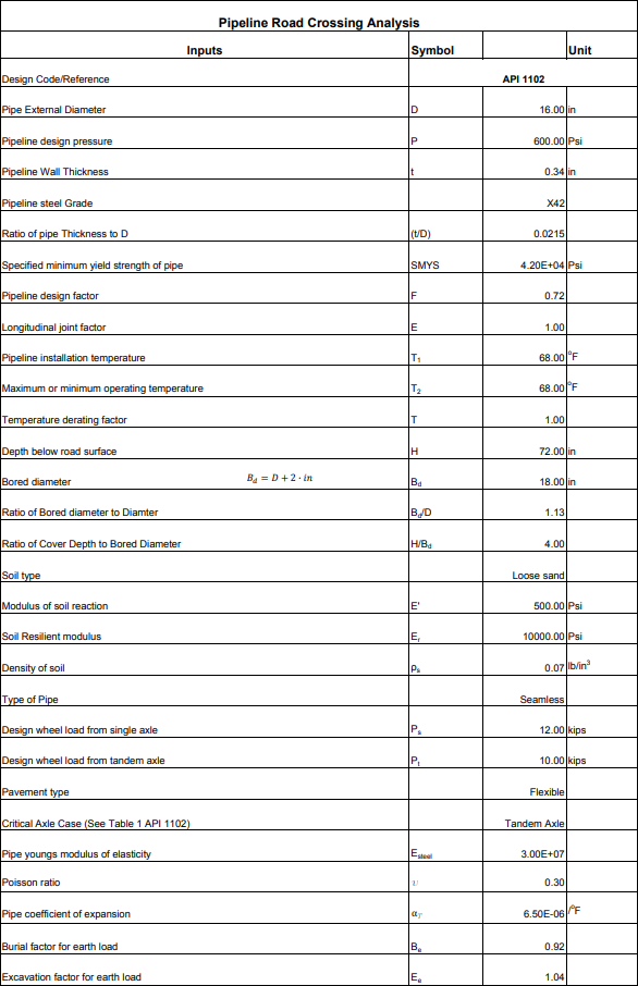
Company A is planning to install a 16” Pipeline to convey crude oil from a processing facility to a refinery. There are various crossing observed along the pipeline route, including a highway crossing. The pipeline crossing the highway will be uncased; the road is made of asphalt. If the proposed pipeline burial depth is 6 ft., check if the pipeline can be safely operated without failure at the highway crossing location.
See below data to be used for crossing design.
Pipeline Diameter = 16”
Pipeline Wall thickness = 0.344inch
Pipeline Design Pressure = 600Psi
Pipeline Material = API 5L Grade X42
Pipeline Specified Minimum Yield Strength = 42000Psi
Pipeline Design Factor = 0.72
Pipe type = Seamless
Longitudinal Weld Joint Factor E = 1.00
Pipeline Installation Temperature = 68oF
Pipeline Operating Temperature = 120oF
Pipeline Installation Technique = Auger Boring
Soil Type = loose sand
Density of Soil = 120lb/ft3 = 0.07lb/in3
Solution
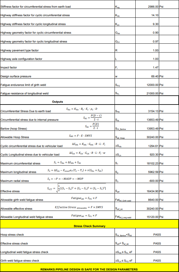
Note some of the factors obtained from figures in API 1102 are approximate values are therefore subject to minor errors.
Using the equations discussed in section 5.0, the results in the attached spreadsheets were obtained.

 To all knowledge