1 Introduction
Pipeline Buoyancy: buoyancy simply means the upward force acting on an object placed in a liquid (Example: water). This force can either make the object float or be lighter than the original weight in the air. Archimedes’ Principle was developed from an experiment to illustrate the existence of buoyancy force. Archimedes principle states that the upward buoyant force that is exerted on a body immersed in a fluid, whether fully or partially submerged, is equal to the weight of the fluid that the body displaces and acts in the upward direction at the centre of mass of the displaced fluid.
Throughout this article, water will be assumed as the liquid medium being considered
1.1 Pipeline Buoyancy
Pipeline buoyancy is one of the major challenges that must be resolved when a pipeline is to be installed offshore, across a river, or across swampy terrain. The pipeline must be analyzed for floatation during the design phase of the project. Any sections of a pipeline subjected to buoyancy force experience bending stress, which may result in structural failure of the pipeline or inline connection failure, such as flange leakage.
The pipeline tends to float when the total downward force, i.e. the sum of the weight of the pipeline and the weight of external corrosion coating, is lesser than the resulting upward force acting on the pipeline. It should be noted that
- The upward force is equal to the weight of the fluid displaced. This implies that a liquid with higher density generates a higher buoyancy force.
- The buoyancy force increases with increasing pipeline diameter. For relatively small-diameter pipelines (NPS < 8), the weight of the pipeline, in most cases, is enough to counter the buoyancy force generated due to the volume of liquid displaced.
2 Pipeline Buoyancy Analysis
Before buoyancy analysis, all data to be used as input must be itemized and documented. Buoyancy analysis performed during Front-End Engineering Design (FEED) may utilize a set level of assumptions; however, during Detailed Engineering, exact and accurate data, such as the density of the medium in which the pipeline will be installed, the density of backfill material, etc., have to be utilized for the analysis.
Before the commencement of buoyancy analysis, a designated minimum safety factor must be set for the project. The factor of safety is the ratio of the total downward forces to the total upward force.
It is recommended that a factor of safety (FS) greater than one be set. Depending on client requirements, a minimum factor of safety of 1.1 is usually recommended, which is also stated for vertical stability in DNV RP F109 section 3.2.
At minimum, the following suggested recommendations shall be utilized for buoyancy analysis;
- The pipeline shall be analyzed for buoyancy where the water level is periodically or permanently above the designed bottom elevation of the pipeline.
- The pipeline shall be analyzed for a case where the pipeline is empty because the weight of the fluid transported will act as an additional factor of safety for the pipeline and the possibility of the pipeline being shut down for maintenance or other reasons without the presence of fluid inside.
- The pipeline shall be analyzed for its end-of-life condition, i.e., the pipeline’s designed wall thickness minus the corrosion allowance added to the calculated pipeline wall thickness. The corrosion allowance acts as an additional factor of safety during the pipeline’s operational life.
- The pipeline is externally coated with corrosion protection material. It is generally recommended that all pipelines installed underground or on water bodies be externally coated.
The thickness of the external coating increases the total outer diameter of the submerged pipe. The total outside diameter must be used for buoyancy analysis. - The minimum pipeline wall thickness shall be utilized for buoyancy analysis. Pipe manufactured according to the API 5L standard can be manufactured with an allowable wall thickness tolerance, which implies that there might be minimal variation in the wall thickness.
The abbreviations below shall be used in the document

Generally, the steps for buoyancy analysis of a pipeline are enumerated in the sections listed below.
2.1 Determination of Pipe Weight
Depending on the pipe specification, the standard weight of pipes can be obtained from various codes and standards. The weight of pipes manufactured according to ASTM or API standards can be obtained from their respective standards.
Conventionally, pipes used in the oil and gas sector are cylindrical. Therefore, the weight of the pipe can be estimated using the formula below

2.2 Determination of External Corrosion Protection Coating Weight
The weight of the corrosion coating applied on the pipeline increases the downward force acting against the buoyancy force. However, this can be neglected. whether the weight is neglected or not, the thickness of the coating must be added to the outside diameter of the pipe. The total diameter shall be used for buoyancy analysis. Generally, pipelines installed underground or on water bodies are coated with external corrosion protection such as polyethene coating (PE coating), Polypropylene coating (PP Coating), etc. The corrosion coating type is a function of the fluid temperature to be transported, as stated in ISO 21809-3 section 7.2. It is assumed in this article that PE coating is utilized for external corrosion protection.
The weight of the PE coating can be estimated using the formula below.

2.3 Determination of Weight of Backfill on the Pipe
The pipeline may be installed on or below the riverbed. Pipelines are also installed on flood plains, swamps and liquefiable soil.
When pipelines are buried, the weight of the soil contributes significantly to mitigating pipeline floatation. The earth pressure acting on the pipeline is equivalent to the weight of a prism of soil width equal to the pipeline diameter and height equal to the pipeline burial depth below the soil.
The soil particles above the crown of the pipeline may be totally or partially submerged, therefore the effect of soil grain buoyancy may be added to the weight of soil on the pipeline.
The formula below can be used to estimate the earth pressure on the pipeline.

Note: the weight of soil shall only be considered in the analysis if the pipeline is installed below ground elevation.
2.4 Determination of Weight of water Displaced
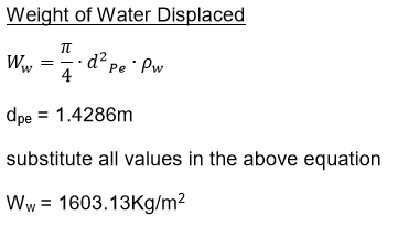
The weight of water displaced by the pipeline is a function of the volume of the submerged cylindrical shape of the pipe. The weight of water displaced increases with an increase in the density of the medium in which the pipeline is installed. The weight of water displaced can be estimated using the formula below.

2.5 Determination of Net Buoyancy Force
The net buoyancy force acting on the pipeline equals the weight of the fluid displaced minus the total downward force (sum of the pipe weight + PE coating ). The soil weight should be added to the downward forces if the pipeline is installed underground. The larger the pipeline diameter, the larger the volume of water displaced. A larger volume of water displaced implies a higher buoyancy force acting on the pipeline. It should also be noted that liquid with higher density exerts a higher buoyancy force on the installed pipeline. Pipelines installed offshore (sea) are subjected to higher buoyancy force than pipelines crossing freshwater rivers because seawater has a higher density than fresh water.
The net buoyancy force acting on a unit length of the pipeline can be estimated using the formula below. A positive value indicates the pipeline will float, while a negative value indicates the pipeline will not float.

2.6 Determination of Bending Stress
The buoyancy force acting on a relatively short section of the installed pipeline acts upward uniformly on the entire length of the submerged pipeline.
The resultant longitudinal bending stress induced on the pipe by the buoyancy force can be estimated using the formula below.

2.7 Factors of Safety Check
Before buoyancy analysis, a required stabilization factor of safety must be set. After calculating all the upward and downward loads, the loads are used to check if the safety factor is met. A minimum factor of safety equal to 1.1 is usually recommended, which is also stated for vertical stability in DNV RP F109 section 3.2. If the set safety factor is not met, mitigation against buoyancy must be implemented as enumerated in section 3.0.
The factor of safety check can be estimated using the below formula’s

3 Pipeline Buoyancy Mitigation Measures
After buoyancy analysis, if the results indicate the pipeline’s tendency to float, appropriate mitigation must be put in place. The approach is simply to increase the downward force, which is an anti-buoyancy force. Before choosing any of the enumerated methods below, the cost implications, installation feasibility, transportation of required materials, and other critical criteria must be considered.
3.1 Increase in Pipe Wall Thickness
This is an easy way of mitigating the buoyancy force acting on the pipeline. It is achieved by selecting a pipe wall thickness that satisfies the designated factor of safety. A cost analysis of this option must be performed in comparison to other solutions, such as continuous concrete coating, etc.
After selecting a higher wall thickness, the buoyancy analysis must be reevaluated to check whether the designated factor of safety has been met.
3.2 Increase in Pipeline Burial Depth
This is achieved by increasing the trench depth where the pipeline will be buried. Increasing the pipeline depth of cover implies a greater volume of consolidated soil above the pipeline, thus increasing the downward load acting against buoyancy force. Consideration must be given to the stability of the trench wall, in swampy terrain increasing trench depths leads to an uncontrollable increase in trench width. Special backfill soil with higher density may also be used in combination with an increase in burial depth to achieve the designated factor of safety. For every selected depth of pipeline cover, the buoyancy calculation should be repeated until the designated set safety factor is achieved.

Figure 1: Pipeline Inside a Trench
3.3 Use of Continuous Concrete Coating
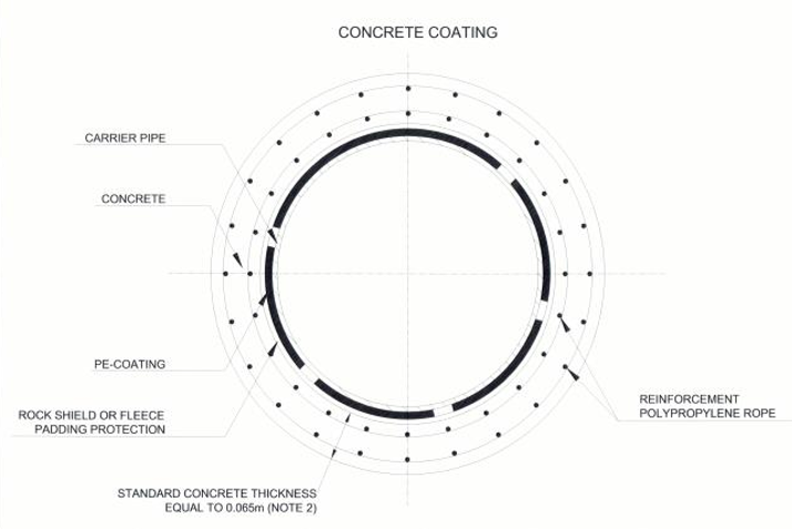
This is the most common method used to mitigate pipeline floatation. Concrete coating required for onshore pipeline river crossings and swampy terrain may be performed on-site or off-site. However, for large-diameter pipelines, the concrete coating is mostly performed on-site along the trench because the weight of the concrete-coated pipe becomes significantly high. It becomes increasingly difficult to transport heavy pipes to the site, which also increases the cost of transportation. See the figure below for the design and installation of concrete-coated pipe.

Figure 2: Designed Pipeline Concrete Coating

Figure 3: Concrete Coated Pipe Installed in Liquefiable Soil

Figure 4: Concrete Coated Pipe Installation, Onshore to Offshore
The concrete coating must be applied appropriately on the pipes to ensure the concrete does not fall off the pipe circumference. This can be achieved by embedding reinforcement, e.g., polypropylene ropes, wire mesh, or other suitable materials installed in layers circumferentially around the pipe in the concrete coating. High-density concrete is preferable for concrete coating because the higher the density of concrete, the lesser the thickness of concrete coating required to counter the buoyancy force.
Large-diameter pipelines require thicker concrete coatings. The density of the concrete mixture can be increased by adding materials of higher density, such as iron ore.
3.4 Use of Concrete Collars
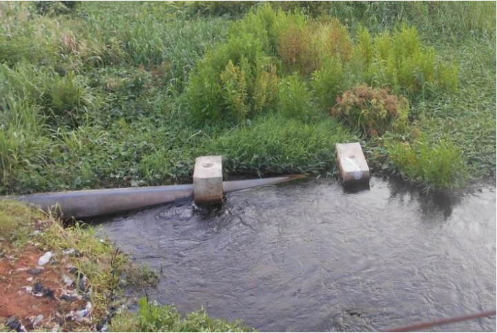
Concrete collars are precast concrete weights. They can be moulded into different shapes depending on the project’s requirements. The weight of each collar must be predetermined. This is added to the downward force used in estimating the anti-buoyancy factor of safety.
Concrete collars must be positioned longitudinally along the pipeline within appropriate spacing because a sag bend or overbend may occur between two successive collars.
Concrete collars are most suitable for swampy locations or places with minimal water depth.
The figure shows an anchor block installed on a pipeline

Some of the limitations of concrete collars are:
- Concrete collars are cast in two pieces and bolted together. They are difficult to install on-site along the pipeline route, especially in swampy terrain. When concrete collars are used for river crossings, they must be preinstalled before the pipeline is towed into position. This is a more difficult task compared to the installation of continuous concrete-coated pipes.
- Generally, for locations with high-level soil erosion or scouring, if the supporting bottom soil is eroded, the weight of the exposed collars will subject the pipeline to an additional external load.
3.5 Use of Saddle Bags
Saddlebags are more applicable for swampy terrains. The bags are factory-made and are designed to carry a maximum designated weight of sand. The bags can be filled on-site with a predetermined soil of known density. The bags are installed in pairs, one on either pipeline side. The result of the buoyancy analysis must specify the maximum spacing between consecutive saddlebags. The weight of the saddlebags within a specified length is added to the weight of the pipe and the external corrosion coating for the buoyancy analysis. It should be noted that the density of the sand used to fill the saddlebags should be significantly higher than the density of the surrounding liquid medium. See the figures below for the typical design and installation of saddlebag buoyancy control.

Figure 5: Designed Buoyancy Control with Saddle Bags

Figure 6: Installed Saddle Bags
3.6 Use of Screw Anchors
Anchors are a factory-made specialized type of anti-buoyancy installation. They are manufactured to resist the mean buoyancy force acting on the pipeline as much as possible.
Anchors are more suitable for locations where they can be easily installed. They utilize the strength of the soil to resist the buoyancy force. The greater the strength of the soil in which the anchors are installed, the higher the buoyancy force that can be resisted. Anchors are mostly used in Liquefiable soil or flood plains. They are driven into the soil below the liquefiable layers (soil layers with appropriate strength) to resist the buoyancy force. Before the installation of anchors detailed survey and soil analysis of the location should be performed, this will determine the minimum depth the anchors will be driven into the soil. Anchors are installed in pairs, one on either side of the pipeline. During the design, the mean design load of anchors, straps, and soil data shall be specified by the engineer, and the manufacturer shall utilize these data to manufacture the anchors.

Figure 7: Screw Anchor Design
4 Worked Example: Pipeline Buoyancy
A 56” Gas pipeline designed as per ASME B31.8 is to be installed onshore. The specified burial depth is 0.8m. After survey activities, it was discovered that a section of the pipeline route is subject to seasonal flooding. The water table occasionally rises to about the ground level.
Perform an analysis to check if the pipeline will float and propose appropriate mitigation.
See pipeline data below.

Solution
The depth of cover 0.8 satisfies the requirement of ASME B31.8 with a maximum depth of cover for location class 4 = 760mm.
At end of life remaining wall thickness = 17.48mm – 3mm =16.05mm


5 Conclusion
Pipeline buoyancy analysis is a key aspect of pipeline design. The level of detail of the analysis may vary depending on the project stage. A set of assumptions for key analysis parameters may be used during front-end engineering design; however, accurate data on key parameters must be used for the analysis during the detailed engineering design stage of a project.
In selecting a buoyancy mitigation measure, factors that must be taken into consideration include cost, ease of installation, and the terrain/soil type of the location where the pipeline will be installed.
Concrete coating is the most widely used buoyancy mitigation measure. However, for large-diameter pipelines, the weight of concrete-coated pipe becomes very high, making installation difficult.
Saddlebags are specialized geotextile bags that are filled on-site with sand. They are more suitable for flooded or swampy soil locations. The density of the sand in the bags must be higher than the density of the surrounding liquid medium. The bags are very easy to install on-site because they can be easily transported to the location where they will be installed.
Concrete collars are sometimes used for buoyancy control and are becoming more applicable to PE pipes. They are precast concrete weight cast in a two-piece. Concrete collars must be installed properly to ensure they don’t add extra stress to the installed pipeline.
EPCM Pipelines
6 References
ASCE: Guidelines for the design of buried steel pipes
API 5L: Specification for Line Pipe
ASME B31.8 – 2016: Gas Transmission and Distribution Piping Systems
Archimedes’ principle: https://en.wikipedia.org/wiki/Archimedes%27_principle
DNV RP F109 – 2007: On-Bottom Stability Design of Submarine Pipelines
ISO 21809-1:2011: Petroleum and natural gas industries — External coatings for buried or submerged pipelines used in pipeline transportation systems — Part 1: Polyolefin coatings (3-layer PE and 3-layer PP)

 To all knowledge