1 Introduction
Gas-fired water bath heaters are a type of heater utilized in a wide variety of settings and industries for process heating. Gas-fired water bath heaters are typically employed in heating processes at lower temperatures (150-250°F) and are used primarily in the processing of oil and natural gas. Gas-fired salt bath heaters achieve much higher temperature ranges (up to 1,000°F) for applications that require significantly higher temperatures. Process heating encompasses several types of heaters, introduced briefly in the section below.
The practice of process heating dates to the first furnaces, kilns, and ovens. Modern industrial practices make use of sophisticated, highly engineered process heaters powered by electricity, fuel, or steam. Process heating may be used to manufacture, or complete industrial processes related to ceramics, concrete, metal, plastics, and more.
Process heaters of all varieties can benefit from reaching greater degrees of thermal efficiency. Achieving this aim is not essential to all forms of process heating, though making greater use of the heat energy process heaters create would aid users across the board.
2 Water Bath Heaters: Industrial Process Heating Basics
2.1 Types of Heaters
2.1.1 Electric-Based Process Heating
Electrotechnologies, or electric-based process heating systems use electromagnetic fields or electric currents to generate heat. Direct and indirect methods of heating are used with Electrotechnologies.
Direct heating methods generate work within the piece by passing a current through, inducing current into, or exciting atoms within the material using electromagnetic radiation.
Indirect heating methods using Electrotechnologies involves using one of the three direct heating methods to heat an element or a susceptor, transferring the heat to the material.
2.1.2 Fuel-Based Process Heating
As is the case with gas-fire water bath heaters, fuel-based process heating involves combusting hydrocarbon-based fuels. The heat generated by this combustion can be directly or indirectly transferred to the material.
The gases produced from combustion can make direct contact with the material, or they may be separated from the material for indirect heating purposes. This fuel-based process heating accounts for at least 17% of total industrial energy use within the United States and may account for 15% or more of production cost.
2.1.3 Steam-Based Process Heating
Steam has several qualities which make it suitable for process heating. High heat capacity, ease of transport, and efficient transfer of heat at constant temperature makes it useful for many process heating applications.
It is fairly common for hybrid systems using steam and another energy source to serve in process heating endeavours. Natural gas or electric-based infrared technology and steam, such as a steam-based drum dryer for paper drying, is one such hybrid system.

Figure 1—Energy sources for process heating operations
2.2 Process Heating Operations Overview
Industrial process heating is used for dozens of heating operations. Industries as varied as chemical production, food production, and metal manufacturing use process heaters for essential operations. The most common heating operations are listed below in Table 1.

Table 1—Process Heating Operations
3 Applications of Gas Fired Water Bath Heaters
Gas-fired indirect water bath heaters are used primarily in the oil and natural gas industries for safe, effective regulation of pressure and treatment of natural gas and oil.
These process heaters are routinely used at compressor stations, power plants, and wellheads to heat natural gas. Heating natural gas while at high pressure prevents the formation of hydrates and ice crystals (Joule-Thomson effect) when pressure is eventually reduced for combustion. This process is critical for preventing significant damage to gas-fired turbines and other equipment.
Oil refineries, offshore platforms, and wellheads use indirect water bath heaters for reducing oil viscosity and processing. When used at a wellhead, water bath heaters (line heaters) maintain temperatures in good operations. Common operations include:
- Heating Feed Stocks
- Heating Natural Gas Before Pressure Reduction
- Heating Natural Gas for Upstream Pressure Regulation
- Heating Process Streams
- Heating Turbine Fuel Gases
- Heating Well Stream Fluids
4 How Water Bath Heaters Work
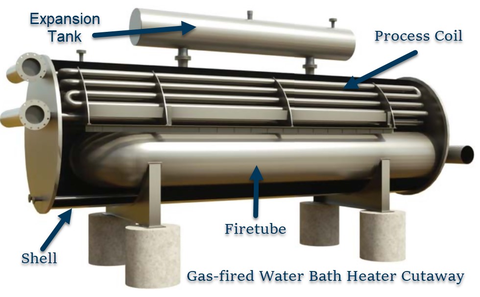
Gas-fired water bath heaters are a type of indirect process heater designed to safely heat product without contaminating it. The heater shell contains the firetube, heating media (water, glycol, or salts), and process coil.
The process to be heated—typically oil or natural gas—flows through the process coil. Carefully controlled heat is introduced into the firetube, transferring heat into the heat media. Process moving through the serpentine coil is heated effectively through convection.
5 Heater Components, Design, and Specifications

Figure 2—Water bath heater shell cutaway
5.1 Heater Shell
The heater shell of a water bath is a vessel designed to operate at atmospheric pressure, containing the firetube, heat media, and process coil. It forms the main body of any water bath heater, with components on both the interior and exterior.
Heater shells must be designed with considerations to current API 12K specifications. The working pressure of a water bath heater must be designed to operate at or near atmospheric pressure, not exceeding 1 psi.
Shells—as well as firetubes, stacks, and supports—will be made from weldable carbon steel (a pipe, plate, shapes, and sheets) which meets suitable grades (ASTM/API grades).
Heater shells may be cylindrical or rectangular. Minimum thickness requirements, allowable stresses, and support design must be meet or exceed API standards. Heater shells are typically leak tested after installation of coils and firetubes, examined for distortions, and repaired deficiencies.
Before water bath heaters are shipped, they are mechanically cleaned and then painted with commercial metal primer. Finish coats may be applied afterwards. If manufactured at this API specification, corrosion-resistant nameplates for the shell and coil will be applied.


Figure 3—Nameplates for shells and coils
5.2 Process Coil
Hydrocarbon gas or liquid flows through the serpentine coil configuration, mounted near the top of the heater shell. This process coil is heated by heating media such as freshwater, water/glycol, or molten salts.


Figure 4—Indirect Heater Coils
Coil design must consider the minimum required thickness or maximum working pressure based on ANSI/ASME B31.3.
The following nomenclature is used in coil design calculations.

The required wall thickness (tr) for maximum non-shock internal working pressure (P) shall be calculated by Equation (1).

The maximum internal working pressure (P) may be calculated by Equation (2).

The working pressure of fittings, flanges, and valves attached to coils must be determined following ANSI/ASME B16.5 or API6A. For proprietary attachments, ratings are supplied by the manufacturer. Internal working pressure maximums must be taken properly into account.
Heater coil sections must be removable from the shell, opposite of the firetube for inspection and repair.

Table 2—Thread Allowance for Pipe Wall Thickness Calculations
5.3 Flue Gas Stack
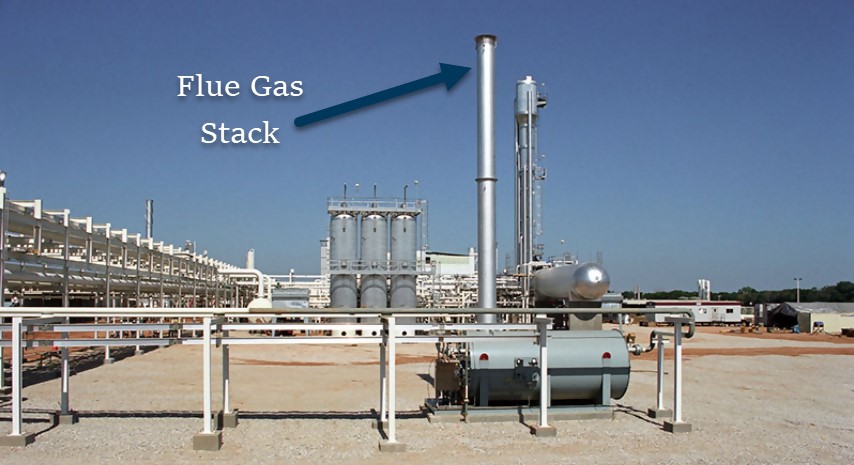
Flue stacks provide a draft for water bath heaters, are covered at the top,
Flue gas stacks should be designed to provide draft capable of overcoming pressure drop in the firetube returns, stack, and flame or stack arrestors. The height of the stack must be considered in conjunction with operating site elevation, with site elevation information provided by the purchaser.

Figure 5—Flue gas stack
5.4 Fire Tube
The firetube adhere to specifications on the purchase order of water bath heaters. It must be removable from the shell, opposite of the coil for inspection and repair.
Firetube heat flux should be within the range of 10,000–12,000 BTU/her/ft2 of exposed area for glycol and water baths.
The heat density of a firetube is regulated by the burner mixer and burner nozzle, with a maximum heat density of 15,000 BTU/hr/in2 for natural draft burners.

Figure 6—Water bath cutaway showing firetube
5.5 Flame Arrestor
Water bath heaters use flame arrestors to aid in regulating fuel temperatures for combustion within firetubes. They achieve this by mitigating flame transmission from the external fuel source.
5.6 Expansion Tank
The expansion tank for water bath heaters contains expanding heating media through operating temperatures. Additionally, it serves to prevent internal corrosion of the heater shell by cycling the wet/dry interface of heating media.

Figure 7—Water bath heater with an expansion tank
6 Performance Improvements
6.1 Efficiency Opportunities
The use of process heating across many industries, usually involving several process heating operations, necessitates systems approach to best utilize process heaters. A systems approach takes into consideration the entire system rather than individual components for maximal effectiveness and efficiency.
Opportunities to improve thermal efficiency with process heaters, in general, are not independent. Heat generation and heat recovery are most often improved by examining the whole system.
Exercises such a transferring heat from exhaust gases (waste heat recovery) to incoming combustion air can reduce energy lost by allowing more efficient combustion of fuel. Advances materials, auxiliary systems, as well as sensor and process controls, are powerful technologies for increasing efficiency in process heating.
Additionally, the U.S. Department of Energy’s Industrial Technologies Program has developed this series of tip sheets through its BestPractices program.
- Preheated Combustion Air (recovery)
- Check Burner Air to Fuel Ratios (generation)
- Oxygen-Enriched Combustion (recovery)
- Check Heat Transfer Surfaces (transfer)
- Reduce Air Infiltration in Furnaces (containment)
- Furnace Pressure Controllers (generation)
- Reduce Radiation Losses from Heating Equipment (containment)
- Install Waste Heat Recovery Systems for Fuel-Fired Furnaces (recovery)
- Load Preheating Using Flue Gases from a Fuel-Fired Heating System (recovery)
- Using Waste Heat for External Processes (recovery)
- Use Lower Flammable Limit Monitoring Equipment to Improve Oven Efficiency
See more at the Office of Energy Efficiency & Renewable Energy Website.
Taking advantage of efficiency opportunities in process heating saves money for industries while reducing energy consumption and reducing emissions. Life-cycle cost analyses are helpful tools for expressing the cost-benefit of investing in efficient water-bath indirect heating systems.
This type of analysis reveals fuel costs for these process heaters comprise up to 90% of life-cycle costs, thus taking measures to increase efficiency by reducing fuel consumption—while not sacrificing productivity or heater longevity—is well worth the investment. Reducing the cost of fuel in this way can be viewed as adding permanent capital to the purchasing company.
7 Summary
Process heating is a vital operation in manufacturing across most industries. Indirect gas-fired water bath heaters are an essential process heaters for processing oil and natural gas.
These heaters are utilized in oilfields, at wellheads, on offshore platforms, in LNG, LPG, and oil refinery facilities within the energy industry. They are designed with high standards, and continually improved through advancements in engineering and technology.
Efficiency in gas-fired water bath heaters, as with all process heaters, is a valuable investment capable of adding permanent capital to companies that invest in achieving efficiency-related improvements.

Figure 8—Diagram of oilfield well heating and treatment using indirect water bath heaters

 To all knowledge