This article explores aspects of seismic analysis of jetties used in the import/export of oil, gas, petroleum and other minerals. The design of jetties in offshore or nearshore waters in seismic active areas often poses challenges with structural analysis and design that other conventional structures do not have problems with. In this article, EPCM explores the conditions that govern the seismic analysis and design of marine jetties and gives some guidelines on how to address these governing conditions.
1 Seismic Analysis of Jetties: Defining a Jetty in the Context of Gas, Oil and Mineral Imports and Exports
The words Pier and Jetty are often used interchangeably, such as LNG Pier or LNG Jetty, both referring to a fixed offshore or nearshore platform raised above the water typically on piled foundations.
In the oil and gas industries, the term Jetty refers to the “Pier” type, i.e. a platform above water used for the porting of oil, gas, minerals and other cargo. This article will use the term “Jetty” and will focus on Jetties used as Port Terminals for Oil, Gas, and other Minerals in seismic active areas.
2 Critical Considerations for the Seismic Structural Analysis of Oil, Gas and Mineral Jetties
2.1 Seismic Active Zone
API 2A 2007 defines a seismic active zone as an area where the Peak Ground Acceleration (PGA) is more than 0.05g. In such cases, the design of the lateral resisting system (the pile and deck frame) is typically governed by seismic actions.
Where PGA<0.05g, the structural pile and deck frame typically is governed by other environmental loads such as extreme tropical storms with high waves, winds and currents or tsunamis.
2.2 Performance Levels/Limit States
The performance criteria for conventional buildings during seismic events are typically only to prevent catastrophic structural failure and not to prevent damage or to maintain functionality.
Due to the high economic costs of repairing marine structures and loss of income during the shutdown, marine jetties typically have to be able to withstand a “frequently occurring” earthquake without any damage, loss of functionality and must be fit for immediate continuation of operations after such seismic event. In extreme seismic events, the structures must still withstand catastrophic collapse, but some damage is allowed.
How does this translate into the analysis?
A jetty structure will have to be designed for two earthquake magnitudes.
For a “smaller, but statistically, for frequent” seismic event, serviceability limit state criteria have to be met while the structure must remain fully elastic (no plastic behaviour). These criteria are usually limiting:
- deflections of structures
- resonance
- strain in connections
- the differential displacement between adjoining structures
For a “larger, but statistically less frequent” seismic event, the structure is allowed to behave plastically. This means that the structure is allowed to experience some damage such as severe concrete cracking or spalling and steel structures are allowed to form plastic hinges. Major repair works would be expected after such an event and operations will typically be halted or limited until the structural integrity of the jetty structures has been restored. Only ultimate strength is considered here.
Ultimate Limit State
For the ULS structural members may be designed to experience some damage, as long as the catastrophic collapse is prevented. Structural members shall be designed using the seismic response spectrum appropriate for:
- 2/3 of the Maximum Considered Earthquake with a 2% probability of occurrence in a 50-year design life, i.e. 2475yr return period
Seismic Analysis of Jetties: Serviceability Limit State
The structure shall be designed to limit deflections, crack widths, differential sway and other serviceability requirements. The structure shall remain perfect elastic and no plastic behaviour in structural connections is allowed.
The seismic response spectrum used shall be for:
- The Mean Recurrence Interval Earthquake with a 10% probability of occurrence in a 50year design life, i.e. 475yr return period
2.3 Seismic Mass
Distribution of Mass
During an earthquake, the ground is accelerating, pulling the structure along with it. Because of the mass accelerating, inertial forces are induced:
Force = mass x acceleration
A unique feature of jetties and marine platforms is that their mass is concentrated at the top of the structure, whereas buildings have the mass distributed throughout the height of the structure. The mass is concentrated far from the soil embedment, cause greater deflections and stresses in the piles.
Loads Contributing to Seismic Mass
It is important to consider all loads that may contribute to the mass that is accelerating during an earthquake. Live loads that may be present during an earthquake should be considered as part of the seismic mass that causes horizontal forces.
Typically loads to be considered as seismic mass:
- Weight of the structure
- Any structures on top of the jetty platform such as control room buildings, catwalks
- All non-structural dead-loads such as screed, parapets, conveyor belts, piping, marine furniture or other equipment and services fixed to the structure
- Any product that may be present such as gas or oil in the pipes, minerals on the conveyor belts, retention ponds
- 30-50% of live loads (depending on how permanent these loads are)
- Any other mass that may be present during an earthquake
2.4 Seismic Analysis of Jetties: Pile Fixity
In order to simplify the analysis of a piled structure, the piles can be modelled as if the structure was fully fixed (like a cantilever) at a depth which is referred to as the pile fixity.
Pile fixity values are typically taken between 3-7 pile diameters. For large pile diameters (D>1.2m) or stiffer soils, lower values of 2D-4D can be used, but a conservative value of 6D is often used for the initial design.

2.5 Scour
Scouring around the pile can be expected due to ocean bottom currents or streams caused by vessel propellers.
If the pile fixity is in the top layer of soil, loss of support should be taken into account in the area of scouring. Scouring can range from 0.5m-1.0m.

2.6 Seismic Analysis of Jetties: Liquefaction
Saturated soils may lose their stiffness and strength and take liquid-like properties due to the vibration of the soil during seismic events.
Any liquefiable layer of soil will not provide sufficient support for piles and the structure should be modelled such that piles are fixed adequately in a non-liquefiable layer of soil.
Pile fixity may not be taken to close above a liquefiable layer of soil to prevent punching through this liquid layer during an earthquake. As a rule of thumb, if the pile is fixed with 3-5diameters above a liquefiable layer, the pile should rather be fixed below that liquefiable layer.
Fixing the piles at a lower level means piles experience more stress due to horizontal loads and deflections may increase due to longer unsupported pile lengths.

2.7 Deflections
Loading platforms, access trestles and other jetty structures that house sensitive equipment or piping are subject to strict deflection criteria that often govern the structural layout and sizes of piles in seismic active zones. Lateral bearing pressure of the soil is critical for seismic design, but pile lengths are usually only governed by normal static conditions.
Overall horizontal deflection is usually limited to between H/400 and H/200, where H is the height from the point of fixity to the top of the deck. Further for access trestles, overall longitudinal deflections are limited to 200mm, overall lateral deflections to span/225 or 100mm. For trestles housing pipes, deflections may even be limited to span/500 to prevent damage of pipes (often containing high explosive products).
For areas of high seismicity, these strict deflection criteria structures often lead to pile sizes of jetty loading platforms and access trestles being much larger than required for strength criteria.
A way of curbing horizontal deflections could be to use a stiffer structure by introducing raked piles and/or larger diameter piles. However, a stiffer structure may experience higher loads during an earthquake, so this might lead to an iterative design process until a structural layout is found that can meet these serviceability requirements.
2.8 Relationship between Slenderness and Force acting on Structure
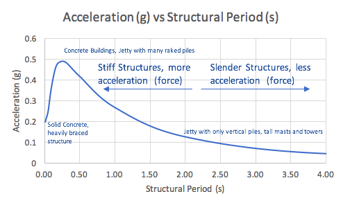
During an earthquake, the fundamental period of a structure (a measure of its slenderness/stiffness) affects how much acceleration, therefore force, a structure experiences during an earthquake.
Slender structures (higher structural periods) such as masts, steel towers or high-rise steel buildings may experience far less force than rigid structures (lower structural periods) such as concrete buildings. Although slender structures experience less force, they deflect more.
Increasing the stiffness does not always reduce deflection sufficiently in an earthquake, because the load increases as the stiffness does.

The design of the structural layout of a jetty needs to find a balance between
- A stiff structure that attracts high loads doesn’t necessarily reduce deflection enough and stresses structural members heavily, and
- A slender structure that experiences lower loads, but does not prevent excessive deflections.
2.9 Loss of Thickness
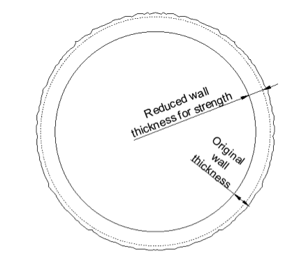
Loss of thickness in the steel piles needs to be taken into account for seismic analysis. The strength of steel piles should be based on a reduced wall thickness, but the analysis should consider the full mass of the pile cross-section.
Typical corrosion rates for structural steel in the splash zone are 0.01-0.03mm/year. Typical rates for design are given by BS-6349 or EN 1998.

Figure 2: Loss of Thickness due to Corrosion
2.10 Seismic Analysis of Jetties: Earthquake Direction and Orientation of the Piles
An earthquake can occur in any direction and due to the “shaking” action, loads are reversible. In the structural analysis of the jetty, all possible directions of seismic action should be considered.
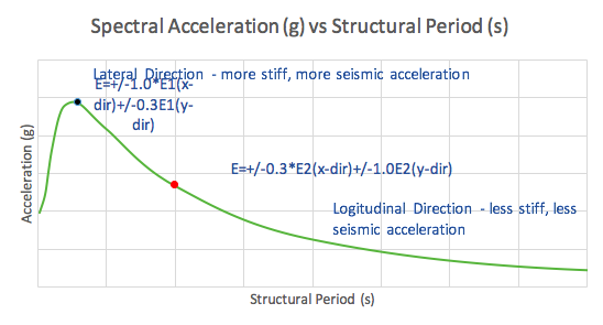
It is common in access trestles that raked piles are orientated in the lateral direction only. Deflection criteria for lateral movement is often stricter than longitudinal movement and longitudinal load are shared between a few pile groups.
This means that the structure is stiffer in the lateral direction than the longitudinal direction. When analysing the seismic event with the dominant direction in the longitudinal direction the seismic acceleration will be less on the structure, because the structure has a higher period of vibration in that direction.

As an example, when analysing the forces in the lateral direction of an access trestle, use 100% of the seismic activity in the lateral direction and 30% in the longitudinal direction. This seismic acceleration based on the stiffness of the lateral direction should be used for this case. In the case where the dominant direction is the longitudinal direction, 100% of the force based on the longitudinal stiffness shall be applied to the longitudinal direction and 30% in the lateral direction.

2.11 Load Combinations
The seismic analysis shall consider the following combination:
(1.0 +/- 0.5PGA)D + 0.3L + 1.0E
Where,
D = loads such as the weight of the structure, fixed equipment, any mass that may be present during an earthquake and loads that occur more than 50% of the time
L = Live Loads: 30% of transient live loads not considered as part of the seismic mass
E = Horizontal earthquake loads as calculated (use D in the calculation to determine seismic mass)
PGA = peak ground acceleration
Berthing, mooring and environmental loads (wave, wind and current) need not be considered in combination with the seismic action.
2.12 Design Codes and Standards for Seismic Analysis
For more detailed guidelines on seismic analysis refer to the literature below:
- EN 1998 – Eurocode 8: Design of structures for earthquake resistance
- API 2A – Recommended Practice for Planning, Designing and Constructing Fixed Offshore Platforms—Working Stress Design
- BS 6349 – Maritime Works
- ASCE 61-14 – Seismic Design of Piers and Wharves (only a guideline, not meant for LNG facilities)

 To all knowledge