Introduction
Hydrogen is envisioned as a “dream” energy carrier that will play a major role in the global transition to a sustainable future. The phrase “Hydrogen economy” has been coined to describe this futuristic vision. Hydrogen is abundant and non-polluting. Large-scale industrial Hydrogen production and utilization has been prevalent for decades, in sectors such as Crude Oil Refining, Ammonia and Methanol. With the global thrust on Net Zero Carbon Emissions by the year 2050, a significant upsurge in Hydrogen demand is expected. It has been projected that global demand of Hydrogen is expected to increase almost six times, from 90 million tonnes in 2020 to 530 million tonnes in 2050. Apart from growth in current industrial user segments, significant new demand will come from power and transportation sectors [1].
The role of pipelines in the Hydrogen supply chain
Pipeline networks that supply Oil and Gas across nations and continents, are an essential facet of global energy supply chains today. For Hydrogen to play a similar role in global energy supply chains, the establishment of large scale Hydrogen pipeline infrastructure would be a crucial factor for success.
Transportation of Hydrogen by pipeline is not a new concept. For example, since 1939, Germany has had a 240 km long Hydrogen pipeline stretching from the Marl Chemical Park to Castrop-Rauxel and Leverkusen [ 2 ]. This 10-inch pipe pipeline transports about 9000 kgs per hour of Hydrogen at 20 barg. The longest Hydrogen pipeline in Europe is owned by Air Liquide and extends 400 km from Northern France to Belgium. In the USA, Hydrogen pipelines are concentrated in the Crude Oil Refining zones along the Gulf Coast and in the Farm Belt. These locations have ready access to Natural Gas, which is used in the Steam Methane Reforming process to make bulk Hydrogen. Estimates of the existing Hydrogen transmission system in the United States range from about 700 to 1300 km [3]. In Canada a 48 km H2 transmission pipeline connects the Air Products Hydrogen production facilities in Strathcona County near Edmonton to customers in Fort Saskatchewan [5]. The Air Products company also operates a Hydrogen production facility, a 30-kilometer pipeline network and a liquefaction facility in Sarnia, Ontario, Canada [6].
Green Hydrogen produced from Water electrolysis by using energy from renewable sources, is likely to become an important source of Hydrogen supply in the future. Completely new Green Hydrogen supply chains need to be established, linking Green Hydrogen production centres to consumers in various markets. Hydrogen markets of the future are going to be quite diverse especially with the growth of zero Carbon transportation and power generation sectors. Therefore, long distance transportation of Hydrogen to diverse markets across vast geographies is inevitable.
While pipelines are the obvious energy arteries for future Hydrogen supply, there is some debate about whether Pure Hydrogen pipelines represent the best way forward. The main driver for this debate is that Hydrogen is viewed as a relatively more hazardous commodity, when compared to gaseous or liquid hydrocarbon fuels. This perception is partly due to its low ignition energy and extremely wide range of flammable concentrations (4 to 75% in air ) when compared to Natural Gas. Hydrogen is also a small molecule that can find many more leakage paths than Natural Gas, and therefore poses a greater leakage risk. People are advocating Ammonia as a safer carrier for Hydrogen, in to mitigate these perceived risks.
While the debate around safety is an important aspect of the discussion around Hydrogen pipelines, there are numerous and significant technical challenges that need to be addressed before large scale deployment of Hydrogen pipelines can be considered. Accordingly, this article deals with the current challenges facing Hydrogen pipeline design.
Classification of Hydrogen pipelines
Analogous to prevailing practices in the Natural Gas industry, Hydrogen pipelines can be classified into transmission and distribution pipelines.
Transmission pipelines:
These pipelines receive Hydrogen from production facilities and transport it to the boundaries of downstream Hydrogen distribution systems. They typically run cross-country, including over public land and third party properties. Hydrogen Transmission pipelines carry large volumes of the gas at relatively high pressures. All existing Hydrogen transmission pipelines are gas pipelines and their operating pressures are less than 100 barg, which is similar to the pressures used in Natural Gas transmission pipelines.
Distribution pipelines:
Their purpose is to receive Hydrogen gas from transmission pipelines and distribute it to individual consumers. The scope transition from Transmission to Distribution typically starts from a pressure reduction station, commonly referred to as a “city gate” station. Distribution pipelines are designed as networks, similar to Natural gas distribution systems, with regulated and metered off-takes to individual consumers. The operating pressure of Hydrogen distribution pipelines is much lower than in transmission pipelines, due to shorter distances, as well as from safety considerations. Distribution pipelines are operated as gas pipelines, though some users such as Hydrogen Vehicle fuel stations could liquefy it within their facilities.
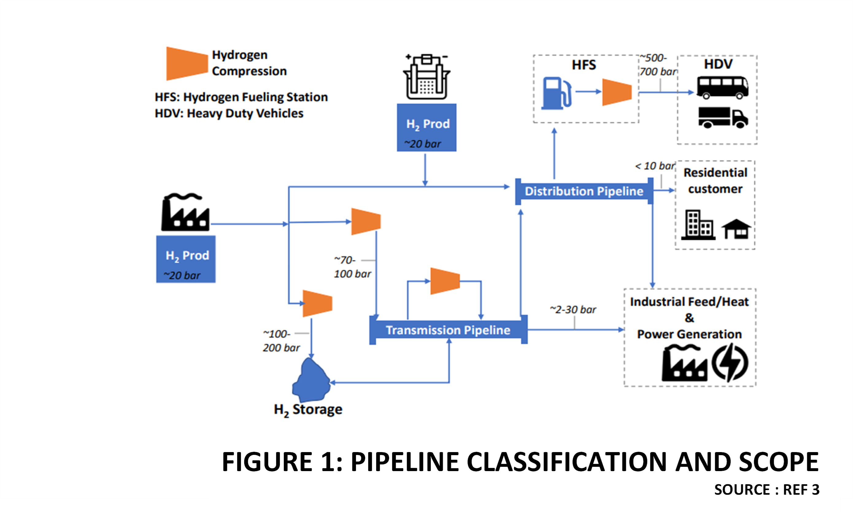
Figure 1 illustrates the scope of the two pipeline categories.
In the context of this article, Hydrogen Distribution pipelines are not complex to design. They operate at relatively low pressure ranges of 15 to 20 barg. Hence well-established industry standards that exist for Hydrogen piping can be leveraged for distribution pipeline design.
The focus of this article, therefore, is on transmission pipelines and the associated design challenges.
System Requirements of Transmission Pipelines
A gas transmission pipeline is not just an isolated conduit but part of an integrated system comprising several subsystems which must work together to deliver the desired functionality [3]. Accordingly, a Hydrogen transmission pipeline system can typically be broken down into the following sub-systems:
Inlet stations:
These fulfil the functionality of measuring and regulating flow of Hydrogen entering the transmission pipeline from various producers. They are equipped with the necessary instrumentation to monitor various process parameters in addition to control, safeguarding, communication and utility facilities. There can be many inlet stations depending upon the number of feeder lines to the main pipeline. Inlet stations are a convenient location for scope demarcation between the Gas producer and the operator of the transmission pipeline. Accordingly, custody transfer metering can be established at these locations.
Transmission pipeline:
This refers to the main pipeline or “Trunk line” that carries the total flow from all the connected suppliers.
Compressor Stations:
The main function of a compressor station is to boost the pressure of Hydrogen received from suppliers to the required pressure of the transmission pipeline. For extremely long pipelines, intermediate booster compressors stations may be needed to compensate for frictional pressure losses. Compressor station are fairly large and complex installations. They are equipped with the necessary remote monitoring, control and safeguarding systems along with communication and utility facilities.
Valve Stations:
All long pipelines have sectionalizing valves which can isolate particular sections of the pipeline based on operational requirements. Transmission pipelines will have several junction where Hydrogen will be received from producers, as well as tapped-off to distribution networks. Valve stations enable these operations to be regulated. Additionally of any segment must be shutdown for inspection or repair, then these sectionalizing valves are useful.
Pig Launcher and Receiver Stations:
Similar to Natural Gas pipelines, pig launching and receiving facilities are required to allow periodic cleaning and inspection of the Hydrogen pipeline. Hence adequate pig launching and receiving stations must be planned at appropriate intervals. They must be provided with all necessary inerting and Hydrogen venting facilities to safely insert and remove the pigs.
Pipeline Monitoring and Control systems
Centralized, remote monitoring and control capabilities are required for Hydrogen gas pipelines. Typical functionalities include flow measurement and regulation, process parameter monitoring, data acquisition and reporting, inventory management, leak detection, emergency alarms and shutdown.
Overview of Hydrogen Pipeline Design Challenges
In spite of longstanding experience with Hydrogen pipelines in Europe and North America, investments in large scale long-distance Hydrogen pipelines have not been forthcoming. Safety and third party liability is one major concern, since Hydrogen poses a higher explosion risk when compared to Natural gas. Apart from accidental leakage concerns, there are known material degradation issues in Hydrogen service, that need appropriate technical analysis. This is especially relevant since future Hydrogen gas pipelines will be much longer and operated at significantly higher pressures, magnifying the risks. Please note that long distance liquid Hydrogen transportation by cryogenic pipelines is not commercially viable, apart from posing increased safety risks.
Eliminating technical and safety risks is an important step towards attracting the necessary investment into the Hydrogen pipeline sector. There is now unprecedented consensus and momentum around establishing a global Hydrogen economy, for which Hydrogen pipelines are essential. This is therefore the opportune time to resolve technical and safety challenges facing large-scale Hydrogen pipeline implementation.
The key challenges in Hydrogen pipelines design can be categorized as follows:
- Low Volumetric Energy Density
- Maximum Pressure limits
- Materials Degradation
- Compressor Design
- Safety
Each of these challenges is discussed in the following paragraphs.
Detailed Discussion Of Design Challenges
Low Volumetric Energy Density
Natural Gas is usually priced in terms of energy content, e.g., Dollars per Million BTU. Since the volumetric energy density of Natural gas is about 1000 BTU/SCF, it takes about 1000 SCF of Natural Gas to deliver 1 Million BTU. In comparison, to deliver 1 Million BTU of Hydrogen energy, 3000 SCF of Hydrogen will be needed. This is because the volumetric energy density of Hydrogen is about one third that of Natural Gas at standard conditions. Figure 2 compares the volumetric energy density of Hydrogen with other competing fuels at various pressures.
If the volumetric energy density of Hydrogen can be increased to match or exceed that of Methane supplied via existing Natural Gas pipelines, then the economics becomes competitive. From figure 2, it is apparent that compressing Hydrogen to high pressures can achieve this objective.
The design challenge here is, what should be the targeted energy density for economic viability?
Given the diverse nature of Hydrogen markets and various other local factors such as the regulatory and policy framework, competing fuels and strategic considerations, there is no “one size fits all ” type of solution.
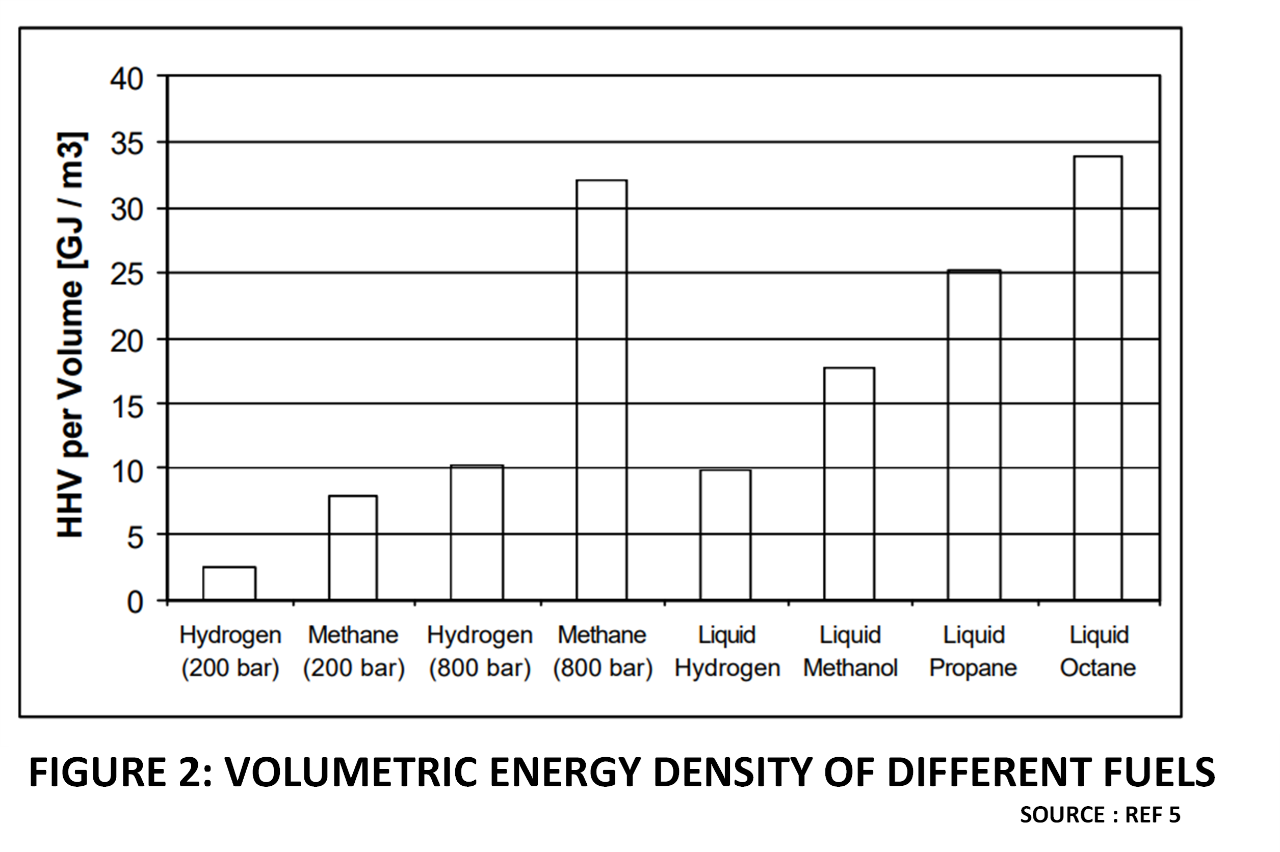
Figure 2
Pipeline Design pressure
This aspect is related to the earlier discussion on energy density. Since higher pressures will increase energy density, it is necessary to investigate any potential upper limits of operating pressure for a Hydrogen pipeline.
Current experience with Hydrogen pipelines in USA and Europe, unfortunately is not helpful in this regard, since are all operate at much less than 70 barg [3]. This is a bit below the pressure at which Natural Gas pipelines are operated and therefore not competitive in terms of energy density. There is a general consensus that the Hydrogen economy will need high pressure Hydrogen to be viable [ 5].
The design challenge here is what is the maximum feasible and safe pressure for a gaseous Hydrogen pipeline?
There is sufficient design and operating experience in the Chemical industry with Hydrogen piping upto 200 barg. In the case of Hydrogen vehicle refueling systems, Hydrogen is compressed to 800 barg. However all these are for in-plant piping traversing relatively short distances when compared to transmission pipelines.
Currently there is inadequate industry experience in operating high pressure gaseous Hydrogen pipelines. This is also an unfamiliar area for pipeline fabricators, contractors and regulatory authorities. There is a lot of ongoing development work in this area to resolve the technical challenges and establish robust regulatory frameworks and industry standards.
As an example of work being done on design standards, the ASME B31.12 Code for Hydrogen Piping and Pipelines now allows the use of high-strength steel that will provide the same margin of safety with thinner pipe walls. Less steel directly impacts the cost of materials and welding. The code is now being updated for further modifications should line-pipes be designed for higher hydrogen gas pressures, up to 340 barg.
In view of the above unresolved engineering challenges, the domain of high pressure Hydrogen pipelines is considered risky. For now, Hydrogen project developers continue to plan their Hydrogen pipelines based on existing knowhow, in the pressure ranges less than 100 barg.
Materials Degradation Challenges
Materials that are normally utilised in Natural Gas pipeline service can undergo degradation in pure Hydrogen environments. For the purpose of this discussion these Material degradation issues can be categorized into :
- Degradation of Pipeline Materials
- Degradation of Polymeric Materials
- Degradation of Instruments
- Degradation of Valve Materials
Degradation of Pipeline Materials
Carbon steel is the default material for any gas transmission pipeline, as it is the cheapest and strongest of all pipeline materials. When deployed in Hydrogen service Carbon Steel is susceptible to damage by Hydrogen embrittlement. Hydrogen Gas Embrittlement affects many metallic materials, including Carbon Steel, Alloy Steels an Stainless Steels. This leads to catastrophic failure by various mechanisms [6]. Due its small molecular size, Hydrogen easily enters and diffuses through the metal surface in contact with it. Plates and pipes formed from metals will have crystallographic defects (dislocations and vacancies) or discontinuities (voids, inclusion/matrix interfaces). Hydrogen accumulates at these locations, causing localized pressure zones which can create minute cracks, making the material susceptible to brittle fracture[7]
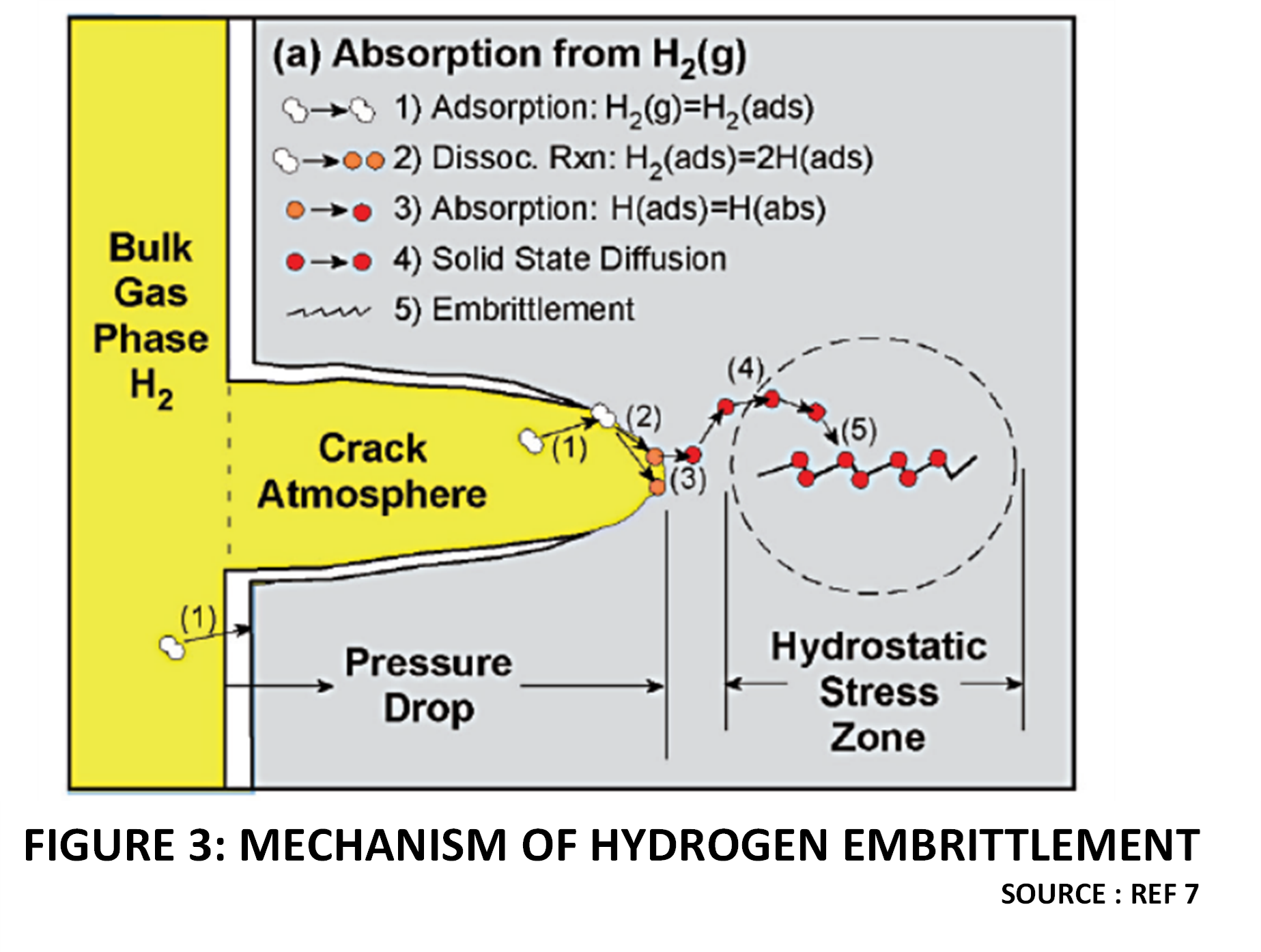
Figure 3 illustrates the mechanism of Hydrogen embrittlement.
The severity and mechanism of Hydrogen damage depends on many variables including :
- Hydrogen source
- Exposure time
- Operating Pressure
- Operating Temperature
- Metallurgy/Metal Processing
- Defects/discontinuity in microstructure
- Surface conditions
- Heat treatment
- Residual stress
- Applied stresses.
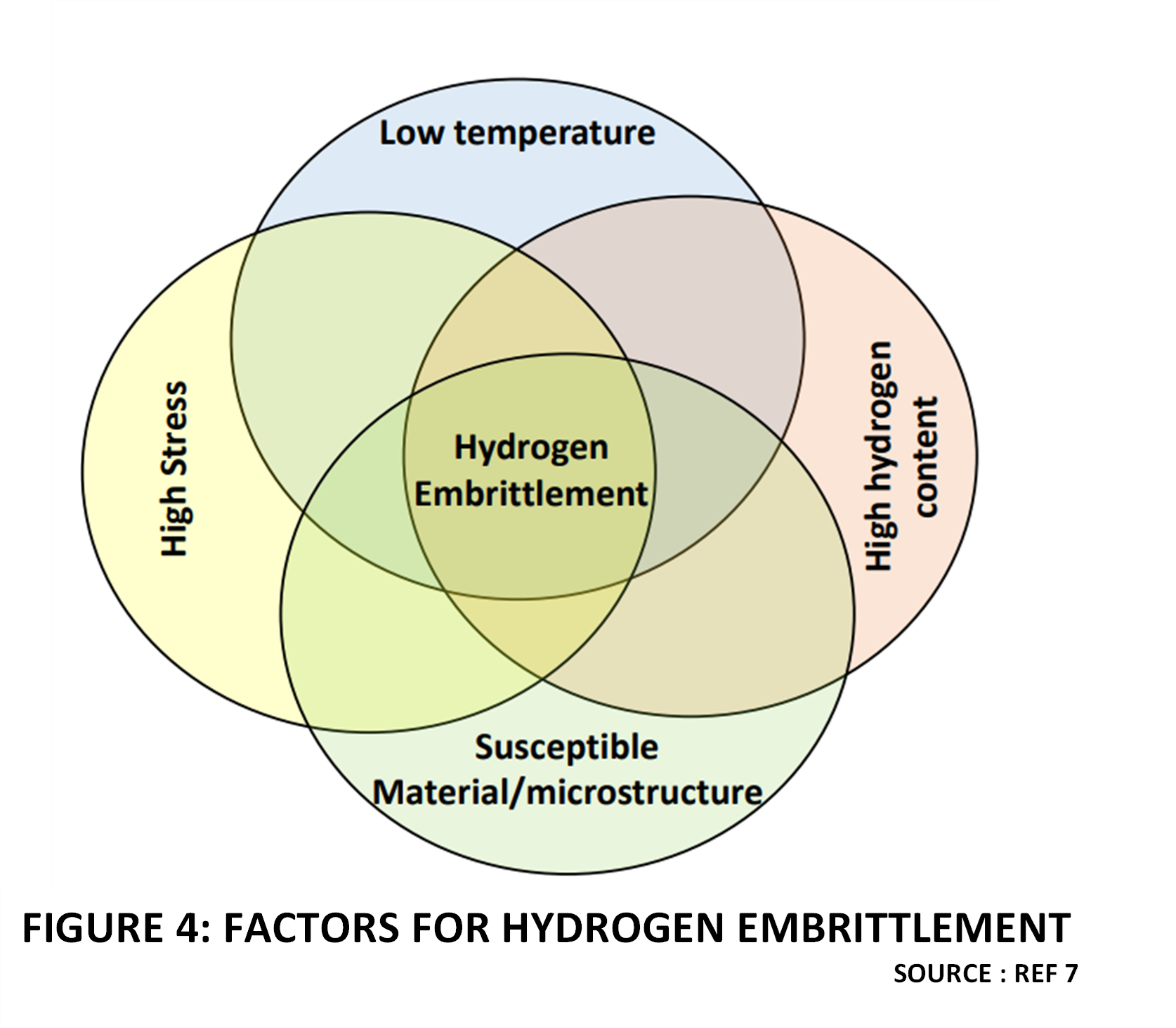
Figure 4 indicates that multiple factors need to coincide to cause Hydrogen damage.
Failure mechanisms that can occur in Hydrogen pipelines, on account of Hydrogen embrittlement are as follows:
- Hydrogen stress cracking (HSC)
- Reduction of tensile ductility
- Hydrogen Assisted Fatigue
These are described in more detail in the following paragraphs.
Hydrogen Stress Cracking (HSC)
Hydrogen Stress cracking describes a phenomenon which resembles stress corrosion cracking seen in oil and gas pipelines, but occurs in Hydrogen gas. In the presence of Hydrogen gas (or Hydrogen blended gas) a combination of material embrittlement and residual or applied stress causes failure well below the usual allowable stress levels. This phenomenon is seen at room temperature for usual metallic materials such as ferritic steels. It does not apply for steels above 150 °C, but could then be replaced at high temperature by “Hydrogen attack”. This failure mode also tends to be negligible at cryogenic temperatures (e.g., liquid Hydrogen), except for some unstable Austenitic Stainless Steels. Susceptible materials may develop minute cracks. Material variables which affect the susceptibility of engineering alloys include alloy composition, grain structure, impurities, hardness and strength. There has to be a sustained load. Generally, the threshold stress for fracture decreases as the yield strength and tensile strength of an alloy increase. This is a matter of concern when using high strength alloys. Hydrogen stress cracking is associated with absorption of Hydrogen and a delayed time to failure which allows hydrogen diffusion into regions of high stress.
Reduction of tensile ductility and notched tensile strength
High pressure Hydrogen gas environments will reduce the tensile strength/ductility and notched tensile strength of susceptible materials. The effect can be tested by comparative tensile tests of candidate materials in Hydrogen and normal or inert environments.
Hydrogen Assisted Fatigue
Acceleration of fatigue crack growth and degradation in fatigue endurance limits in high pressure Hydrogen environments have been observed. Carbon and low alloy steels show such degradation even at relatively low pressures in Hydrogen gas. This is a mechanism which should be considered, preferably avoided, if possible, in such applications. Reciprocating compressor piping must be analysed for the effect of pulsations. Pipelines that experience a lot of line-pack/ unpack and pressure fluctuations as well as offshore pipelines must consider this risk.
Finally, it is pertinent to point out that a lot of the literature on this subject makes a reference to “Hydrogen attack” which is a damage mechanism different from those discussed above. This is a phenomenon that only occurs at high temperatures, not normally encountered in transmission pipeline service. Hydrogen attack of a Carbon Steel or low Alloy steel involves the reaction of Carbon in the steel with hydrogen to form Methane which results in crack formation. The resultant loss of Carbon is called “Decarburization” and reduces the mechanical strength of Steel. Austenitic Stainless Steels are resistant to Decarburization and Hydrogen attack.
The “Nelson Chart” in API 941 shows operating limits for Carbon and low alloy steels with respect to Hydrogen partial pressures and corresponding temperature [6]. In fact, in selecting Carbon steel with operating temperatures below 500°F, the partial pressure of Hydrogen can exceed 3000 PSI (not indicated on chart) without worrying about Hydrogen attack. That is why this failure mode is not relevant for pipeline design. However, pipeline welding involves elevated temperatures and is a risk factor for Hydrogen attack in the heat affected zone. Hence in all cases, Carbon steel should be post-weld heat treated. The weak point in an all welded system will be the flange joint. Number of flanges should be minimized in a Hydrogen pipeline and the joints must be properly designed.
Degradation of Polymeric Materials
The utilization of synthetic polymers in Hydrogen pipelines and associated equipment occurs broadly in the following areas :
- Sealing Applications
- Lining Applications
- Pressure Containment Vessels and Pipes
Polymers that are used in high pressure Hydrogen services include :
- HDPE (Pressure Vessel liners )
- POLYAMIDE (Pressure Vessel liners )
- EPOXY RESIN COMPOSITES ( glass/ carbon fibre vessels and pipes )
- PTFE (seals)
- PEEK (seals )
- NITRILE RUBBER (O-rings and gaskets )
- FLUOROELASTOMER ( O-rings and gaskets)
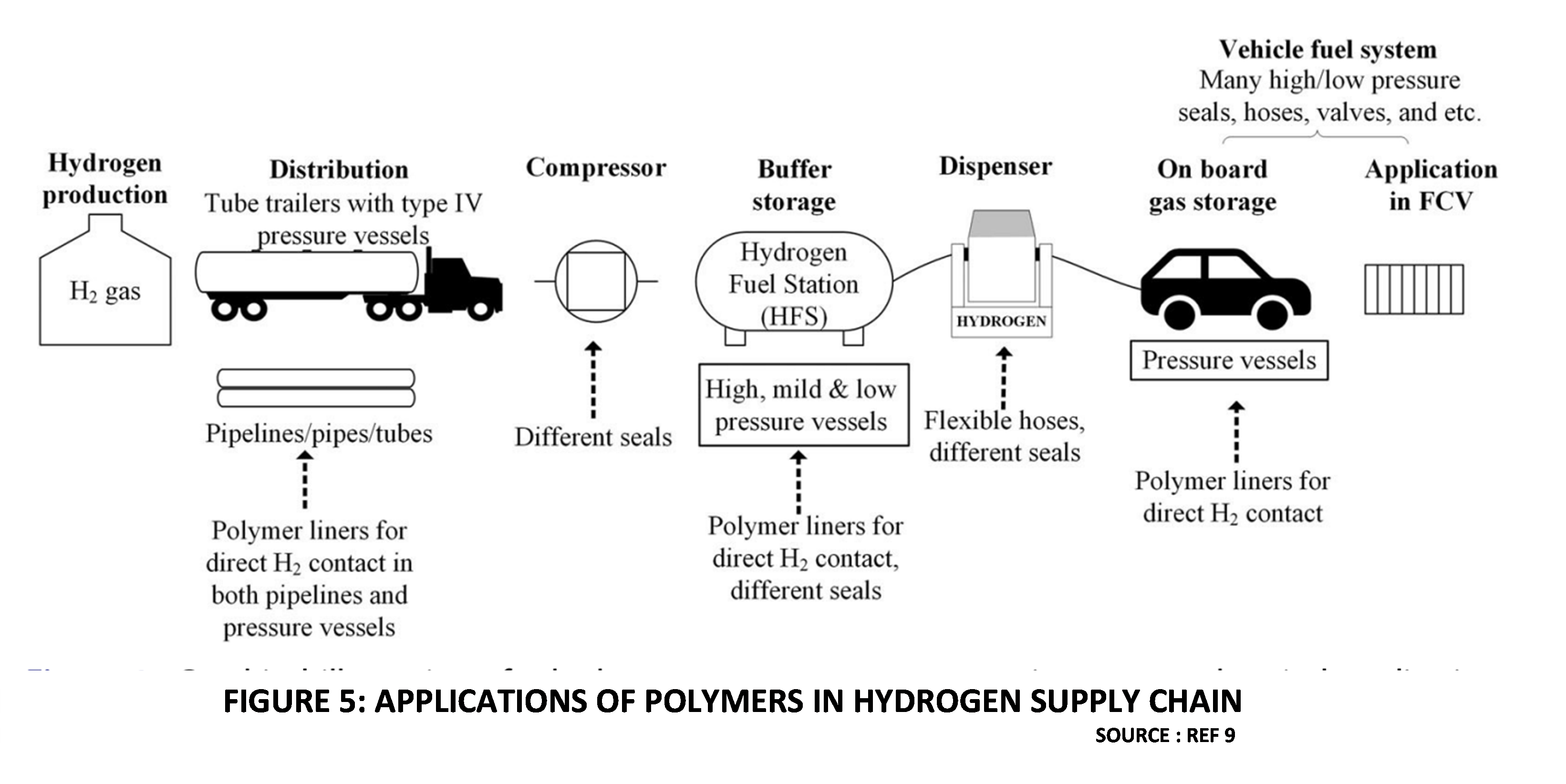
Figure 5 illustrates the areas where polymers find application in the Hydrogen supply chain.
Due to its small molecular size, high pressure Hydrogen penetrates the macromolecular network of polymer chains. The overall process is driven by the solubility and diffusivity of Hydrogen in the Polymer matrix. The accumulation of molecular Hydrogen within the polymer matrix changes many physical properties of the polymer leading to its failure in the desired application.
Some important damage mechanisms are as follows [9]
RGD induced damage of elastomers and thermoplastics
High-pressure exposure and subsequent rapid decompression often lead to cavitation and stress-induced damage of the elastomer due to localization of the Hydrogen gas. This is called Rapid Gas Decompression (RGD) and is a major cause of failure of elastomeric sealing and lining components. It also leads to failure of thermoplastic lining materials.
Swelling induced damage of elastomers
Swelling and consequent deformation caused by Hydrogen permeation and accumulation changes the dimensions of elastomeric sealing element. Additionally, the mechanical properties are affected. Eventually this leads to Hydrogen leakage.
Aging Related Degradation
Long term exposure to high pressure Hydrogen affects the properties of elastomers use for sealing as well as lining materials. Hence frequent replacement of these elements is needed, which is not a practical proposition in critical services such as Hydrogen transmission pipelines.
Degradation of Instrument Materials
In respect of metals used in instrument tubing the same embrittlement issues and failure mechanism that were discussed for pipelines is relevant. In any case, Carbon steel is not used for process connections to instrumentation. There are two specific aspects related to instruments that are worth highlighting to engineers as follows :
Embrittlement Induced Failure of Rupture Discs
We have discussed the reduction of tensile ductility and notch tensile strength due to Hydrogen embrittlement. There have been cases where premature failure of rupture discs have occurred due to this cause [6]. This is an aspect to be kept in mind while deciding the disc material as well as the installation design.
Hydrogen Gas Entrapment in Transmitters
Hydrogen atoms and molecules can permeate through barrier diaphragms and enter the transmitter’s fill fluid. Over time, the fill fluid becomes saturated. It may happen that the bubble point of the liquid is reached, and free Hydrogen bubbles are seen. In terms of quantity this is not immediately hazardous. However, the trapped gas causes zero and span shifts over time degrading performance of the transmitter. Further, over time, increased accumulation and associated pressure causes failure of barrier diaphragms leading to transmitter failure through the loss of fill fluid [10]. Whenever transmitter are used in safeguarding applications, especially HIPPS systems, this is one aspect to be considered in the design.
What are the possible mitigation measures to address this problem? Selection of the appropriate Diaphragm Materials is important. The atomic lattice spacing varies in different metals and this influences the rate of Hydrogen permeation. The nickel (Ni) content of the metal also affects the rate of Hydrogen permeation which increases exponentially with the Nickel content. Stainless steel has the lowest Nickel content and is the diaphragm material of choice for most applications. The most preferred option if one can afford it, is gold-plating the barrier diaphragms. A thin layer (0.00012 inch (3 μm) thick) of 99.9% pure Gold virtually eliminates Hydrogen permeation without itself being affected by the process.
What is the life expectancy of transmitters in these conditions? Gold plating is a good long-term option since the expected operating life of a transmitter is extended 5 to 10 times this way. It has been reported that in pure hydrogen services at 200 °C and 150 barg pressure, a Hastelloy C-276 diaphragm failed after 6 months in service. By contrast, the transmitter life was 4 years with gold-plated diaphragms while Stainless steel diaphragms in this service last 3 to 5 times longer [10].
Temperature also plays a role in longevity of diaphragms in Hydrogen service. The operating life of a transmitter increases by about 33 to 40 times per 100 °C temperature reduction. From the perspective of transmission pipelines where operations are usually in the ambient temperature range, this is not a concern. There may be some issues within compressor systems. There is a small effect of operating pressure as well on diaphragm life. Reducing the static pressure from 150 barg extends the operating life by about 20% per barg.
To summarize, the instrument designer dealing with transmitter for high pressure Hydrogen environments must keep the following guidelines in mind.
- Select a suitable diaphragm material ,including gold plated types.
- Keep the temperature of the diaphragm as low as possible.
Degradation of Valve Materials
Valves involve the use of metal castings, wrought materials as well polymeric sealing elements. Hydrogen embrittlement affects the steels used in valves in the same manner that it affects pipes and plates. Similarly, polymer degradation has also been discussed.
The additional factor of interest related to valves is “Hydrogen blistering” [11]. This term describes the formation of blisters caused by Molecular hydrogen (H2) accumulated at internal defects such as voids, laminations, and non-metallic inclusions. The accumulation results in increased pressure inside the defect cavities, eventually causing blistering of the material. Killed steels are more resistant to Hydrogen blistering than non-killed steels due to their relative lack of internal voids. The term “killed” actually only pertains to wrought products; however, cast steels are also deoxidized with elements such as Silicon or Aluminum to prevent the formation of gas porosity.
Compressor Design
Historically, positive displacement compressors such as reciprocating and diaphragm types have dominated Hydrogen compression applications in industry. This is primarily because the majority of industrial Hydrogen compression requirements have been for medium pressure and high pressure Reactor feed and recycle loop applications in sectors such as Ammonia, Hydrotreatment and Hydrogenation. The relatively low flow rates and high pressures in these applications are in the recommended performance range of positive displacement compressors.
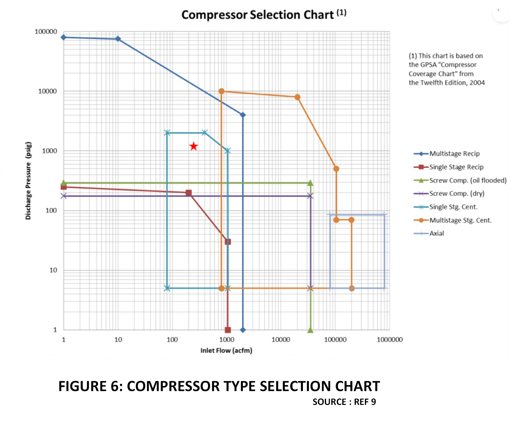
Figure 6 illustrates the basis for compressor type selection.
However, Hydrogen pipelines of the future will require compressors that can deliver high flows at high pressures. While multistage reciprocating types can at deliver pressures upto 800 barg, they cannot deliver the high flows that would be needed for transmission pipelines. It would not be a viable proposition to have a large number of compressors in parallel to do the job due to any capacity limitations.
The obvious way forward then, is to plan for centrifugal compressors, which are the conventional choice for Natural Gas Pipelines. Unfortunately, the design of centrifugal compressors for Hydrogen is very challenging, due to its low molecular weight. Typically, when compared to Natural Gas, the impeller tip speed for Hydrogen compression needs to be three times higher [4]. The industry is working on integrally geared centrifugal compressors for Hydrogen pipeline service that can function at higher tip speeds. However, this is still a work- in-progress and is one of the important design challenges to overcome.
Another aspect is energy efficiency of Hydrogen compression, when compared to Natural Gas. Figure 7 shows that the power requirement for Hydrogen compression is significantly higher than for a corresponding Natural Gas application [5]. Designing high efficiency centrifugal compressors is therefore a significant challenge to make Hydrogen pipeline transport competitive.
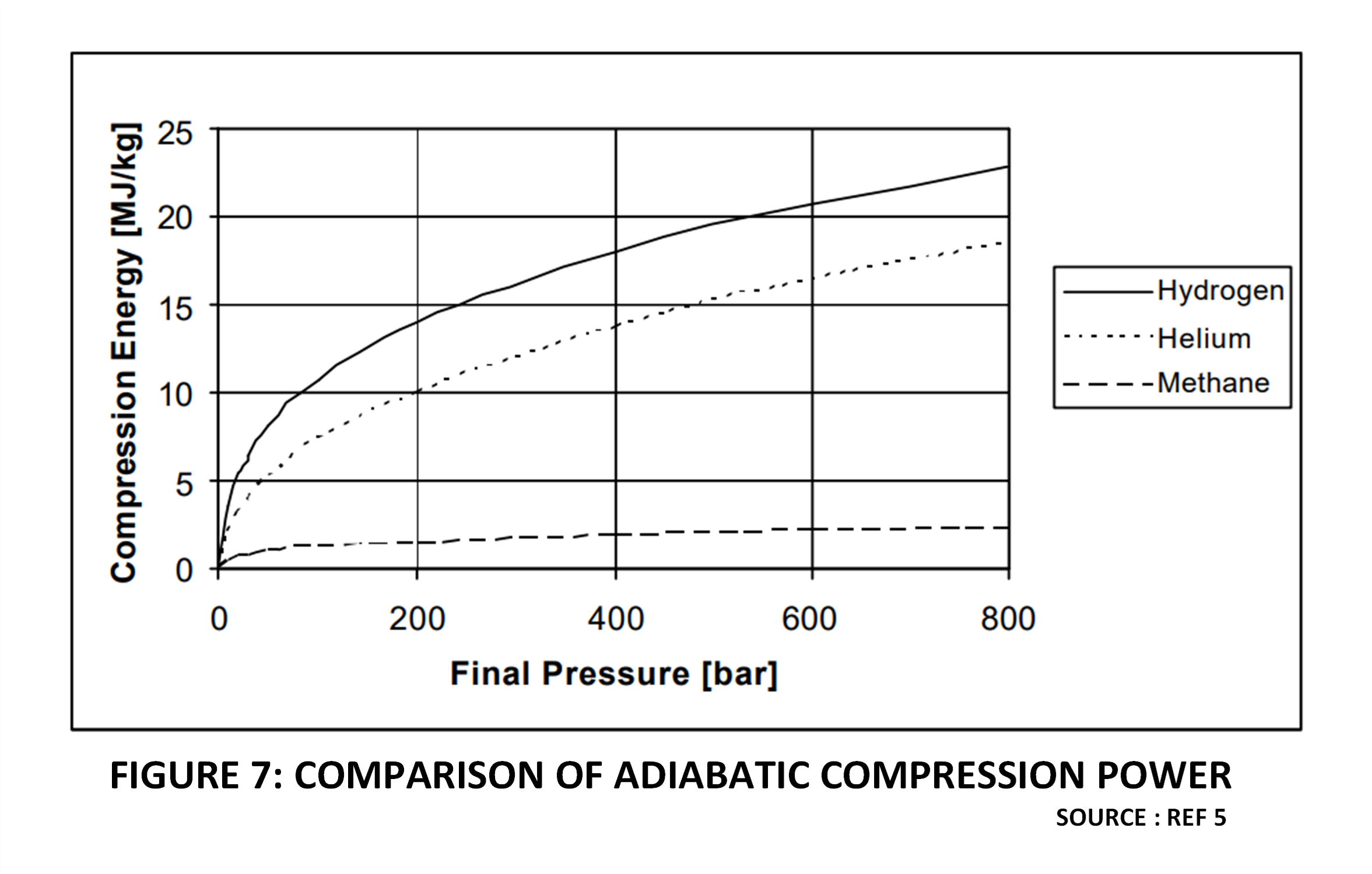
Figure 7
Safety Challenges
The biggest concern with Hydrogen pipelines is uncontrolled leakage from a high-pressure pipeline. There are three important risk factors that make a Hydrogen leakage much more dangerous than a comparable Natural Gas leakage. These risk factors are as follows:
Low Minimum Ignition Energy
The minimum ignition energy of Hydrogen in Air is one of the lowest among gases at 0.02 millijoules. In comparison, the minimum ignition energy of Natural Gas is about 0.3 millijoules.
This means that a leaking Hydrogen cloud can be ignited by a spark with less than one-tenth of the energy needed to ignite a similar Natural Gas cloud. Thus, special attention is required to prevent sparks by appropriate hazardous area classification, grounding, bonding and other measures to prevent static electricity build up. This includes velocity restrictions within vent piping and also in pipelines if there is a risk of static build-up.
Wide limits of flammability
The lower and upper flammability limits of Hydrogen in Air range from 4% to 75% by volume. In comparison, the corresponding limits for Natural Gas are 7% and 20% by volume. The comparatively wide range of concentrations within which Hydrogen can ignite therefore magnifies the risk posed by its extremely low ignition energy.
Joule Thomson Inversion
The Joule Thomson inversion temperature for Hydrogen is very low. Even at one atmosphere pressure and ambient temperature, Hydrogen gas heats up when expanded. Thus, Hydrogen gas leaking out from a crack in a high-pressure pipeline could heat up very quickly and increase the risk of ignition.
Given the above heightened risks associated with Hydrogen leakages, how efficiently can Hydrogen gas leakages be detected? Obviously, transmission pipeline leakages cannot be monitored by thousands of instrumented Hydrogen Gas detectors. The cheapest and most practical method would be to dose a suitable odorant, similar to what is done in the case of Natural Gas and LPG pipelines. This is easier said than done. There is no known odorant light enough to “travel with” Hydrogen. Development work is ongoing to find a suitable Odorant that meets the criteria for detectability and would not contaminate the end users’ operation. This is therefore an unresolved challenge both in engineering terms and from a regulatory perspective.
References
- Global Hydrogen Review 2021, IEA.
- Hydrogen Pipelines and Hydrogen Grids, TUV Nord Hydrogen pipelines for safe transport | TÜV NORD – Hydrogen | TÜV NORD (tuev-nord.de)
- Overview of Interstate Hydrogen Pipeline Systems, by J.L Gillette and R.L Kolpa, Argonne National Laboratory, 2007.
- The Techno-Economics of Hydrogen Pipelines- Technical Brief, by Mohd Adnan Khan et.al, TRANSITION ACCELERATOR TECHNICAL BRIEFS, Volume 1, Issue 2 , November 2021; Technical Brief: The Techno-Economics of Hydrogen Pipelines – Transition Accelerator
- Energy and the Hydrogen Economy, by Ulf Bossel and Baldur Eliasson; Energy and the Hydrogen Economy
- Hydrogen Transportation Pipelines IGC Doc 121/04/E Globally Harmonised Document, European Industrial Gases Association.
- Stress Engineering Services Inc. SES Doc. No.: 2021-03-11 E
- Workshop on Hydrogen: Infrastructure Challenges and Case Studies, Greenberg Traurig, 11 March 2021, Germany.
- A Review On Applicability Limitations And Improvements Of Polymeric Materials In High Pressure Hydrogen Gas Atmospheres, by Winoj Balasooriya et al. Polymer Reviews, February 2021.
- Hydrogen Permeation – Hydrogen Applications, Honeywell Application Note
- Virtual Valve Basics, valve Magazine, April 2008 ; Specifying Valves for Hydrogen Service | Valve Magazine
- compressor-screening-tool-fig1-1024×745.png (1024×745) (empoweringpumps.com)

 To all knowledge