Introduction
Green Hydrogen is projected to be a significant component of the global energy mix, as the world shifts to low-Carbon fuels and sustainable energy sources. Green Hydrogen is produced by the electrolysis of Water, utilizing renewable electricity, to ensure that the production process is free from Carbon Dioxide emissions.
The global demand for Hydrogen in 2019 was 115 million tonnes, comprising 70 million tonnes of pure Hydrogen and another 45 million tonnes as a constituent of mixtures such as syngas or producer gas [1]. The demand for Hydrogen is widely projected to reach 500 million TPA by 2030, due to new demand for Hydrogen fuels from the transportation, power generation and industrial sectors.
Hydrogen’s attractiveness as a fuel is due to its excellent calorific value and absence of Carbon Dioxide emissions upon combustion. Additionally, Hydrogen is an established fuel and feedstock, especially in major sectors such as Crude Oil refining, Fertilizers and Steel plants. Technical knowhow, industry standards and procedures related to Hydrogen are well-developed. With regard to the newer applications of Hydrogen, it is noteworthy that Hydrogen fueled cars, buses, trucks and trains are commercially available and operating. The transition to a Hydrogen fueled economy in the coming decades is backed by global consensus amongst the major industrialized economies. and the investment community. Over the next few decades, polluting fossil fuels are expected to be phased out with Hydrogen, renewables, nuclear and other clean technologies catering to global energy demand. Current Hydrogen production methods that rely on fossil fuels will be replaced primarily by Green Hydrogen, which involves splitting Water using renewable electricity. Regular announcements in the media of upcoming mega-projects indicate that there is momentum towards making Green Hydrogen a mainstream energy source.
In most countries and global forums, the advocacy of Green Hydrogen has been largely focused on its decarbonization benefits. However, there is a rarely debated, but significant downside to Green Hydrogen and that is Water consumption. Stoichiometrically, about 9 kg of pure Water is required to produce 1 kg of Hydrogen by electrolysis. Additionally, Water is required for electrolysis stack cooling and also for some Balance of Plant equipment, though purity requirements are less stringent.
The Water demand for Green Hydrogen must be seen in the context of the overall Water demand for the energy sector. A study by the IEA concluded that energy-related water consumption would increase by nearly 60% between 2014 and 2040. While it is recognized that some renewable technologies, for example Solar PV and Wind require negligible Water, others like Biofuels, Concentrated Solar power, Carbon Capture and Storage (CCS) and Nuclear power are associated with significant Water consumption, mainly in the Balance of Plant sections [2].
The IEA has warned that if the Water demand related to energy transition is not properly managed, it could cause great distress, particularly in major populous and developing economies like China and India, where many existing thermal power plants are often located in Water scarce areas, near fuel supplies. The IEA report makes some key recommendations directed at policy makers as follows:
- Integrate energy and water policymaking
- Co-location of energy and water infrastructure,
- Utilisation of the energy embedded in wastewater,
- Using alternative sources of Water for energy and improving the efficiency of both sectors.
Currently there are only two technologies that are being utilized for large-scale commercial Green Hydrogen projects. These are Alkaline Water electrolysis (AWE) and Proton Exchange Membrane cells (PEM). Both AWE and PEM electrolysis technologies require high quality Water as feedstock. Inevitably, to minimize Water treatment costs, it is necessary to utilize good quality raw Water from terrestrial freshwater sources. If Green Hydrogen production grows as projected, then it will adversely impact the availability of freshwater at the locations where these projects are established. Many parts of the world are already struggling with the degradation and depletion of freshwater resources due to population growth, industrialization, urbanization, deforestation, pollution and intensification of agriculture.
The existence of all forms of life on planet Earth, whether plant, animal or human depends on availability of adequate terrestrial supplies of freshwater. Communities can be expected to resist giving up their freshwater resources for the privilege of obtaining Hydrogen fuel. Furthermore, supply chain trends indicate that Green Hydrogen may be produced at lower costs in developing countries with plenty of sunlight or wind power and exported to lucrative Hydrogen markets in industrialized nations. This business model can certainly be challenged from an ESG perspective, if freshwater depletion at the Hydrogen producing locations is considered.
The future of Water electrolysis, as a pathway for Hydrogen production, is therefore dependent upon overcoming potential sustainability challenges associated with freshwater consumption. This aspect is recognized within the electrolysis industry and there is a lot of research and development work aimed at avoiding or reducing the use of freshwater. Alternative approaches that have been proposed include options such as using seawater, treated industrial effluents and treated sewage. Unfortunately, in all cases the fact remains that current commercial designs of AWE and PEM electrolyzers cannot tolerate salts or impurities.
Figure 1 illustrates the conventional approach to using Water from various sources for Green Hydrogen production [3]. It can be inferred that not only does Water treatment complexity increase with contamination, the quantity of raw water to produce one cubic meter of ultrapure Water also increases. Wastewater discharges from the Water treatment plants due to Reverse Osmosis (RO) reject streams, or operations such as backwashing and regeneration, would also increase. It has been estimated that the Capital expenditure on an RO-based Water treatment unit is about 22% of the Balance of plant (BOP) for a commercial scale PEM electrolyzer. For example, the cost of a 1200 m3/d throughput Reverse Osmosis plant is about US$ 2 million. The operating expenditure of Water purification plants is also significant, ranging between $ 2 to $ 3 per m3 of Water throughput [4].
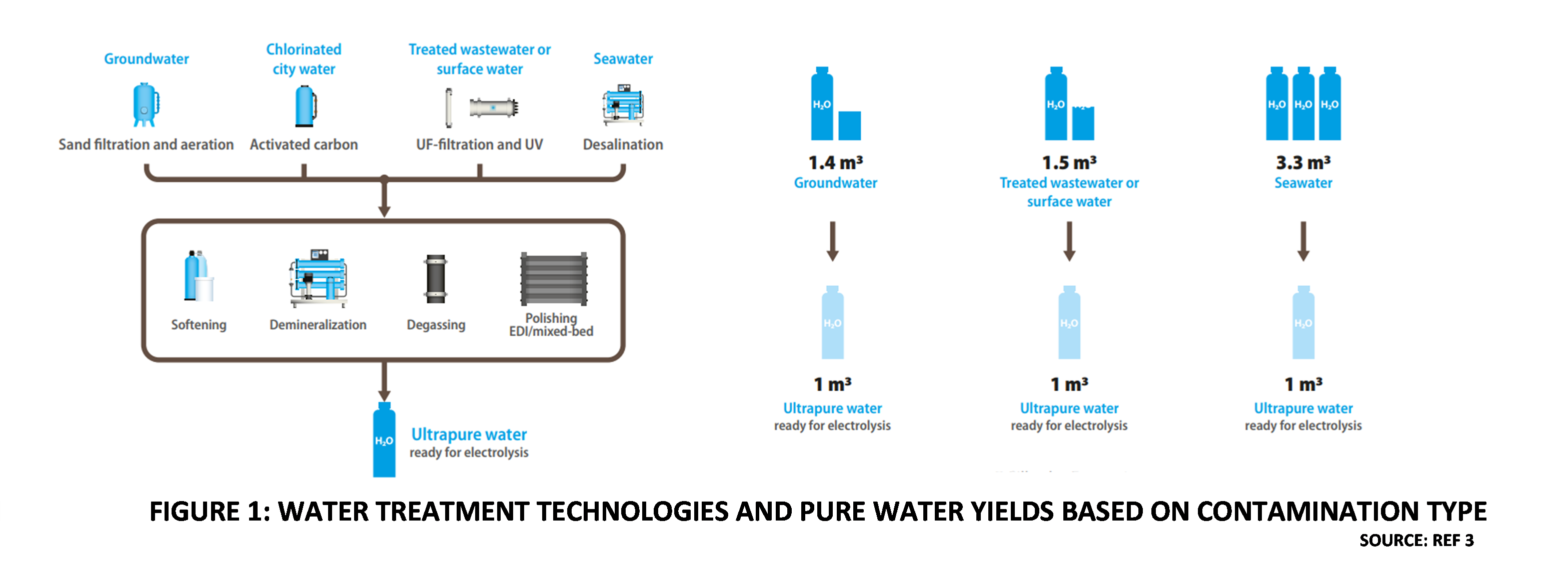
Figure 1
Today, there are multiple “green” technologies available to manufacture Hydrogen, that do not consume Water or consume less Water than electrolysis. For example, Hydrogen technologies based on Methane splitting consume negligible or no Water at all. These technologies can also use renewable electricity and have negligible Carbon footprints. If Green Hydrogen has to compete with alternative pathways for sustainable Hydrogen production, then electrolysis technologies must aim to minimize freshwater consumption while producing Green Hydrogen at competitive cost. It is heartening to note the significant amount of research and development work being reported on seawater, brackish water and wastewater electrolysis. Seawater and brackish water electrolysis have a long history in the electrolytic production of Caustic Soda and Chlorine. Wastewater electrolysis, however, is an emerging field. Much of the research in this area has been focused on pollution control methods that utilize electrolysis to remove non-biodegradable and ionic pollutants in various industrial wastewater. While these studies demonstrate that cost effective electrodes can be developed to function in highly contaminated wastewaters, it is doubtful if anything can be leveraged from this for Green Hydrogen electrolysis technology. Green Hydrogen production involves the use of extremely expensive catalysts and membranes, and it would be disastrous to expose these materials to highly contaminated Wastewaters. Green Hydrogen production installations involve hundreds of interconnected electrolysis cells, so the impact of contamination would be huge. Treated Wastewaters, however, offer a realistic option that the Green hydrogen Industry is actively exploring. It is technically feasible and makes both economic and ecological sense. This article therefore takes treated wastewater as a starting point, to examine various aspects of wastewater electrolysis for Green Hydrogen production.
What are the issues related to treated wastewater electrolysis? Can electrolysis cells deal with the higher levels of impurities in treated wastewater? What are the fundamental reasons why ultra-pure water is currently a requirement for Green Hydrogen electrolysis plants and can the threshold levels for impurities be increased? If yes, then what are the impurities that can be permitted and at what levels?
To answer these and related questions it is first necessary to get a basic understanding of present day electrolysis technologies used for Green Hydrogen production. In the following sections, this article provides an overview of the main electrolyzer technologies that are commercially deployed. Thereafter, the impact of impurities in Water on electrolysis performance is explored, based on published information. Subsequently, various research and development approaches towards wastewater electrolysis and ongoing projects on green Hydrogen from Wastewater are summarized.
Overview of Electrolysis technologies
Working principle
Water is a stable compound, and energy must be externally supplied to break intramolecular bonds. In electrolysis, energy in the form of direct current electric supply is used to split Water into Hydrogen and Oxygen. The electrical energy is applied as a DC voltage across the positive and negative electrodes of an electrolysis cell. Electrons enter the cell from the DC circuit though an electrode called the Cathode, which is negatively charged. The other electrode where electrons leave the cell to enter the external circuit, is called the Anode and is positively charged. The Voltage difference between the Anode and Cathode provides the driving force for electric current within the cell. The liquid within the electrolysis cell must be an electrolyte, which means that it must be sufficiently ionized, to be able to conduct electricity. An increase in the electrical current means that more energy is available for electrolysis. Water, which is weakly ionized into H+ (proton) and OH– (hydroxide) ions, is a weak electrolyte and not sufficiently conductive, to enable efficient electrolysis. For the purpose of electrolysis at commercial scale, the conductivity of Water is increased by using strong acids or alkalis which increase the concentration and availability of H+ or OH– ions respectively. When the electrolyte is acidic, then the main charge carriers within the liquid are H+ ions, which move toward the negatively charged Cathode, due to the potential difference. Conversely when the electrolyte is alkaline, the main charge carriers within the liquid are OH– ions, which move towards the positively charged Anode.
At the Cathode, H+ ions combine with electrons from the external DC circuit to form Hydrogen atoms. These nascent atoms then spontaneously combine with other Hydrogen atoms to form Hydrogen molecules. This is termed the Hydrogen evolution rection (HER) . Similarly, OH– ions formed by the ionization of Water molecules further split into Oxygen atoms and protons. The negatively charged electrons are released at the Anode, while Oxygen atoms combine to form Oxygen molecules. This is called the Oxygen Evolution Reaction (OER). Electrons collected by the electrode move to the external circuit, maintaining the current flow. Figure 2 illustrates the working principle of liquid Water electrolysis [5].
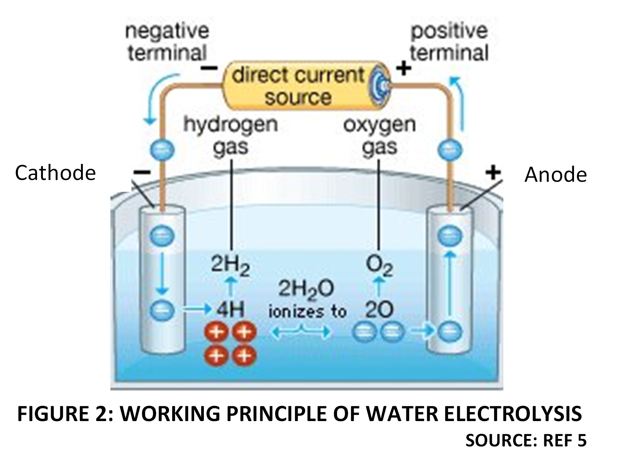
Figure 2
The theoretical minimum voltage to split Water into H2 and O2 in an electrolysis cell is termed “reversible cell voltage (𝐸𝑟𝑒𝑣 )” and is calculated as 1.23 Volts. In practice however, there are many types of voltage losses due to resistances at the electrodes and within the electrolyte. This results in irreversible dissipation of energy in the form of heat produced by electric current passage through the resistances. The term “thermo-neutral” voltage is used to describe the cell voltage that considers these energy losses and is therefore the theoretical minimum voltage that is needed to perform the electrolysis reactions. The thermoneutral voltage for liquid Water electrolysis is 1.48 Volts, under standard conditions [6].
In reality, commercial electrolysis cells operate at higher voltages than the thermoneutral voltage, due to many factors, such as need to maintain higher current density, compensating for various degradation mechanisms and effect of impurities. Since electric current provides the energy for the water splitting reaction, increasing the current density, while minimizing voltage losses is an important consideration in electrolysis cell design. Commercial scale electrolyzers for Green Hydrogen incorporate several features to improve the energy efficiency, increase current density and reduce overvoltage. The Anode and Cathode, in addition to conducting electricity between the external circuit and Water, also function as holding surfaces for catalysts. The presence of a catalyst facilitates electrolysis reactions by reducing the energy requirements. The components of a typical Water Electrolysis system are :
- Individual electrolyzer Cells.
- Electrolyzer Stack, comprising numerous individual cells assembled together.
- Balance of Plant typically consisting of electrical DC power system, feed water system, cooling water system, liquid separation, de-oxygenation, gas drying, Hydrogen compression, storage, control and safeguarding systems, safety and fire protection systems.
As mentioned earlier only PEM and AWE electrolyzers are currently utilized for commercial scale green hydrogen project. Their key features are summarized below:
Alkaline Water Electrolysis
AWE technology is more than hundred years old and is well established in the industry. This technology is comparatively cheap, as it does not use Platinum group metals (PGM) as catalysts at the electrodes. The alkaline electrolyte in commercial AWE cells is typically a 20%-30% solution of Potassium Hydroxide in pure Water. The Anode and Cathode are kept apart by a porous diaphragm or separator, which is generally made from advanced composite materials like ZIRFONTM diaphragm (Zirconium Dioxide and hydrophilic polysulphone polymer). The purpose of the diaphragm is to separate the electrodes and prevent mixing of Hydrogen and Oxygen gases. The construction of an AWE stack with multiple cells can be Unipolar, where the Anode and Cathode in each cell are physically separated by the intervening diaphragm. Bipolar designs are also used, in which the electrodes are designed to have dual polarity. This means than one side of the electrode acts as Anode while the other side acts as Cathode for the adjacent cell in the stack. Due to the alkaline environment, nonprecious metals such as Nickel, Cobalt and Iron, which are more stable to dissolution, are used as a catalysts. Commercial systems predominantly use Nickel-based catalysts [4].
The external DC power source has its negative terminal connected to the AWE Cathode, where two molecules of Water are reduced to one molecule of Hydrogen (H2) by incoming electrons, and two Hydroxide ions (OH–) are produced. The produced Hydrogen is collected from the Cathode surface and piped out, while Hydroxide ions transfer through the porous diaphragm to the Anode, driven by the difference in voltage between the electrodes. At the Anode, two Hydroxide ions release electrons, forming Oxygen (O2) molecules and Water.
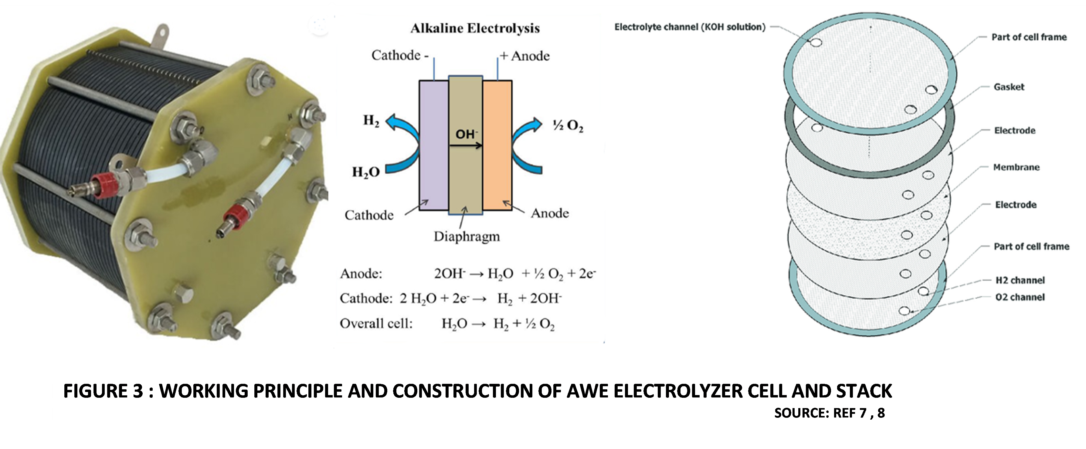
Figure 3 shows the working principle and construction of an AWE cell and stack [7,8].
Proton-Exchange Membrane Electrolysis
Protons are the ionic charge carriers in a PEM electrolyzer. The Protons are produced at the Anode by releasing electrons to the external DC circuit. They migrate across the polymer membrane electrolyte, to the Cathode. At the Cathode the Protons combine with Electrons from the DC electric source, to form Hydrogen gas.
The heart of any PEM electrolyzer is the polymer Cation exchange membrane. This is a thin membrane, with Cathode and Anode catalyst layers coated on either side, forming what is called catalyst-coated membrane (CCM). Generally used catalyst deposition methods include spray coating and screen printing. The membrane is usually based on Perfluorosulfonic acid (PFSA) with a hydrophobic backbone of Polytetrafluoroethylene (PTFE). Other options for membranes, such as Polyetheretherketone (PEEK) and Polybenzimidazole (PBI) are available [4,7]. The PFSA structure comprises a Perfluoroethylene side-chain and a hydrophilic Sulphonic acid head group, which ensure high ionic conductivity.
The most popular membrane commercially is NafionTM, which is a PFSA membrane developed by Dupont. The catalysts and membranes are all high cost items. Due to the corrosive nature of the acidic polymer electrolyte, expensive materials like Platinum and Palladium are used as catalysts at the Cathode while, Iridium oxide and Ruthenium Oxide are typically used at the Anode. The Porous Transportation Layer (PTL (also called Gas Diffusion Layer, GDL) can be made from sintered Titanium via powder metallurgy or from Carbon cloth. It must have the necessary porosity to effectively transport gases and liquids by diffusion. The CCM is sandwiched between the Anode and Cathode electrodes. This sandwich, together with the PTL is termed the Membrane Electrode Assembly (MEA) [11].
Bipolar end plates are used to separate adjacent cells in a electrolyzer stack. They have small channels to enable the transport of Water, Hydrogen, and Oxygen inside the stack. One side of each Bipolar plate contacts the cathodic side of an MEA, while the other side of the plate contacts the anodic side of the adjacent cell’s MEA. Bipolar end plates are usually made of Titanium [4].
PEM catalyst layers also contain an ion conducting phase, which increases the electro-chemically active surface area. This is the surface where the reactant (Water), ions (Protons) and electrically conducting phase (catalyst surface) are in close contact. This ion conduction phase, termed Ionomer is also a PFSA [4]. Figure 4 illustrates the working principle and construction of a PEM electrolyzer.
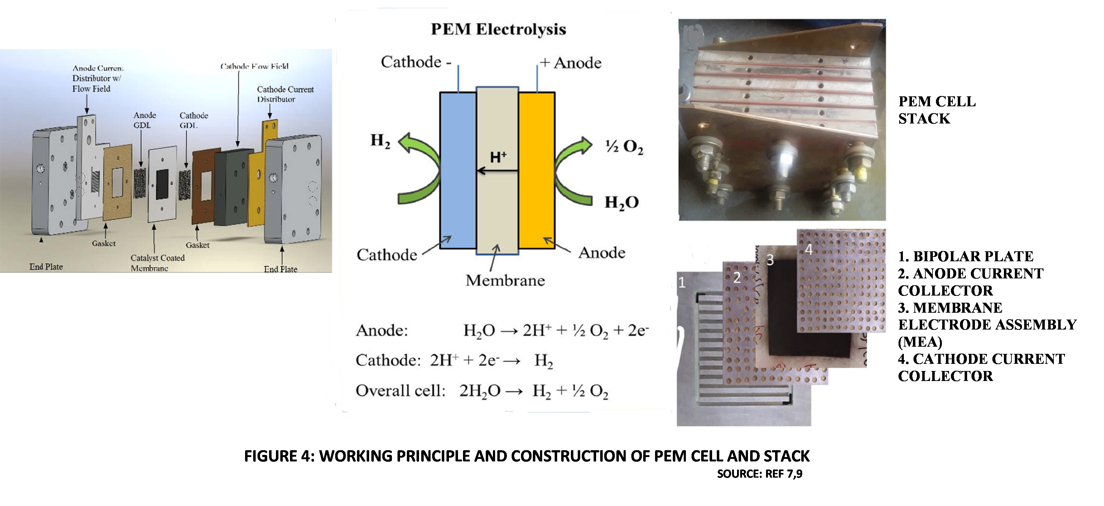
Figure 4
Impact of Impurities on Electrolyzer performance
Wastewater treatment and recycling technologies to produce Tap Water or Potable Water from industrial wastewaters and Sewage are well-established. There are numerous example of such installations all over the world. A typical treatment scheme is shown in Figure 5. However, Tap Water or Drinking Water contain mineral salts and other impurities at permissible levels for human consumption. They do not meet the ultra-pure Water quality specifications typically required by present day AWE and PEM electrolyzers. As a first step towards utilizing treated wastewaters electrolyzer technologies are sought to be improved so that it becomes feasible to directly use Tap Water as feedstock within an electrolyzer for Green Hydrogen Production.
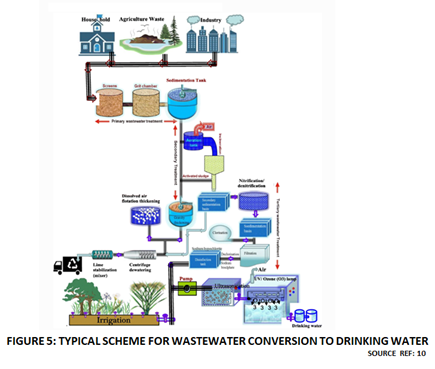
Figure 5
Treated wastewater can contain many types of impurities, including, dissolved salts, dissolved organics and suspended solids. The final composition of the treated wastewater depends on the nature of raw wastewater and the extent of treatment that it has undergone.
In industrial settings, treated wastewater is more likely to be of Cooling Water quality, whereas in urban settings, treated wastewater may comply with Potable Water or Tap Water specifications. However, the sources of impurities in commercial electrolyzers are not restricted to external impurities that enter with the feed Water. Many impurities are generated within the electrolyzer cells and BOP systems, due to degradation of materials, side reactions, contamination during manufacturing, commissioning or maintenance. These can be termed endogenous impurities [4]. This occurs in both AWE and PEM electrolyzers.
For the purpose of this discussion of this discussion, impurities are categorized into:
- Ionic impurities
- Dissolved organics
- Suspended solids
The effects of these impurities on electrolyzer performance are a matter of considerable research. The following sections summarize some of the known impacts, as reported in published literature.
Ionic Impurities
Membranes and Catalysts are the key electrolyzer components impacted by ionic impurities.
Ionic impurities in Water can be positively charged ions (Cations) or negatively charged ions (Anions). The Cations move towards the Cathode and the Anions move towards the Anode of the electrolyser due to the electrical potential difference.
Impact of Cations
Cations are particularly harmful for PEM cells since the polymer (PFSA) membrane is a Cation exchange membrane. Hence, Cations that have greater affinity for the Sulfonic acid group will displace H+ ions from the membrane. For example, Sodium (Na+) ions are almost always present in treated wastewaters. In fact, even highly purified freshwater Water used for PEM cells may still contain 5 mg/ litre of Na+ ions and 5 mg/litre Cl– ions, while complying with the typical conductivity limit of upto 1.0 micro siemens/cm. On the basis of this loading, it has been estimated that a 1 MW capacity PEM Water electrolyzer stack may, over a decade of operation, be exposed to over 40 grams of Sodium ions, which displace Protons in approximately one third of the Cation exchange membrane.
Cations also degrade PEM cell performance and lifetime by affecting the catalyst and Ionomer layers. The main mechanisms of Cationic degradation in PEM electrolyzers are [4]:
- Substitution of available Protons in the membrane and Ionomer. This leads to reduction of membrane ionic conductivity (increased resistance to electric current).
- Adsorption and Deposition of metallic Cations on the Cathode, reducing the electrochemically active surface area.
- Initiation of unfavourable reactions. For example, Iron (Fe2+) contamination may initiate the Fenton reaction with any Hydrogen Peroxide formed during Water electrolysis. The Peroxide is decomposed to Hydroxy radicals, which then damages the polymeric backbone of PFSAs, causing membrane thinning.
In the case of AWE cells, the main charge carrier is an Anion (OH–). Hence Cationic impurities do not disturb the charge transfer efficiency or directly impact the electrodes and membranes. Cationic impurities can adsorb or deposit onto the electrodes. Adsorption or deposition on the catalyst can sometimes be helpful; certain impurities like Nickel and Iron which are normally used in the Catalyst coating, increase the reaction rates at the Anode and Cathode. However other Cationic impurities like Zinc, Cadmium and Lead have been shown to degrade electrode performance [4].
Impact of Anions
In the case of PEM cells, Anionic impurities are not as harmful as Cations. One reason is that Anions cannot replace Protons within the membrane and Ionomer. However other problems such as the initiation of side reactions may affect the performance. For example, the presence of sufficient Chloride ions could result in Chlorine evolution along with Hydrogen and also corrode metallic components. The Chlorine evolution reaction is the main reason why Seawater or Brackish water is not directly used for Green Hydrogen production. Other Halogen atoms such as Fluorides, Bromides and Iodides would behave in the same manner, forming the respective Halogen gases.
Chloride ions are also corrosive to Platinum used in the cathode Catalyst. The Chloride Anions form Chloroplatinic ligands that enhance Platinum dissolution, Since other PEM cell components such as PTL and Bipolar plates also have Platinum coatings to minimize contact resistance, they can be similarly attacked by Chloride ions.
Chloride Anions not problematic for alkaline electrolysis and there is a long history of operating electrolyzers with Sodium Chloride brine solution in the Chlor-Alkali industry. However, Nickel Catalyst used in the electrodes of Water electrolyzers can be corroded by Chlorides. The presence of Carbonate Anions or Carbon Dioxide gas, however, has been shown to lower the performance of AWEs by reducing the electrolyte conductivity.
Impact of Organic impurities
Organic impurities do not change the electrical conductivity. Treated wastewater will almost certainly have permissible amounts of organics and microbial constituents. In PEM cells, there are two routes by which performance can be adversely impacted by organic contaminants:
- Poisoning via adsorption of species on the catalyst surface, decreasing electrochemical activity.
- Enhancing catalyst dissolution.
In AWE cells, organic contaminants may be oxidized in the presence of Nickel catalysts. The oxides may passivate the Nickel catalyst. Direct poisoning by organic contaminants is also possible. Additionally, gases such as Carbon dioxide and Carbon monoxide may be produced by Oxidation, which adversely affect the AWE cell performance and contaminate the Hydrogen product.
Impact of Suspended Solids
In both AWE and PEM electrolyzers, contamination by suspended solids leads to clogging of pores in components such as PTL (or GDL) and Diaphragm. This obviously interferes with effectiveness of ion movement across these components.
Table 1 summarizes the effect of various impurities on AWE and PEM electrolyzer performance [4].

Research and Development on Green Hydrogen from Wastewater
Monash University Study
Monash University has teamed up with several national utilities in Australia, including Southeast Water, Melbourne Water, Yarra Valley Water and Water Corporation via Water Research Australia (WaterRA), to study the potential use of wastewater for the process of electrolysis. This is part of the university’s Sustainable Hydrogen Production from Used Water project (SHPUS) which aims to address the challenge of Water scarcity by repurposing wastewater as the feed for electrolytic Hydrogen Production. The research aims at initially developing a complete understanding of the impacts of water impurities in used Water on the performance and durability of Water electrolysers. Thereafter, guidelines will be developed for designing improved Water electrolysers and upgrading existing wastewater treatment plants [12].
From an economic perspective, Australia’s plans to bring in $10 billion to the Australian economy each year through the sale of more than 3 million tonnes of green hydrogen and/or ammonia by 2040. This project therefore has environmental as well as economic significance.
Green Hydrogen Feasibility Study at Al Ansab Sewage Treatment Plant, Muscat Oman
Oman is an oil producing country with large tracts of desert. Freshwater is a precious resource, found in only a few places. However , decarbonization goals are important for Oman and sought to be achieved sustainably. A feasibility study was carried out at the Al Ansab sewage treatment plant in Muscat, Oman, on Green Hydrogen production ui8ng treated effluent from the sewage treatment plant [13].
The effluent leaving the sewage treatment plant contains significant amounts of organic contaminants, as seen from the BOD (Biochemical Oxygen Demand) loading, which averages 480 kg/day. Suspended solids are at a similar level, while Nitrates and Ammonia loadings are also high. The treated effluent is also Chlorinated before storage. This study considers Reverse Osmosis technology to treat the effluent to meet ultrapure Water specifications required by the electrolyzers. Unlike the Monash project approach, the pathway here is conventional, based on the feedwater quality limitations of current electrolyzer technologies. The study evaluates only PEM electrolyzers. Solar PV along with battery storage was considered for renewable electricity supply. Two cases were studied, with capacities of 1,500 kg H2/day and 50,000 kg H2/day and were shown to produce revenues of 8.30 million OMR/year and 49.73 million OMR/year, respectively. This is an interesting result that should grab the attention of many municipalities since, in general, sewage treatment plants have negligible scope for generating revenue.
Ardmore Distillery, Kennethmont,UK
Aptly named “WhiskHy”, this project located at Aberdeenshire distillery will use wastewater a a feedstock for producing Green hydrogen by electrolysis. The, project involves installation of an electrolyser The phase 1 feasibility study for the US$ 4.5 million project has already been completed. The project is in phase 2 of demonstration. During this demonstration phase, the WhiskHy team expects to produce almost 165,000 bottles of “zero carbon dioxide” whisky per year, leading to annual CO2 emission reduction of 71 tonnes [14].
Power Plant Boiler Wastewater
This theoretical study investigates a preliminary design for producing Hydrogen from the wastewater of coal utility boilers via an integrated photovoltaic (PV) and electrolysis system. This study is interesting because Boiler wastewaters are rich in dissolved salts but have negligible organic impurities. Parallel solar panels and series PEM electrolyzer cells are coupled into optimal integrated arrangements. Energy losses including activation and ohmic losses, plus the required energy for compressors and pumps are considered in the model. Effects of the working temperature, solar irradiation, and charge transfer coefficient are investigated. The calculated efficiency of the PEM electrolyzer and PV solar panels range between 60–62.5% and 18–20%, respectively.
References
1.0 The Future of Hydrogen, Report prepared by the IEA for the G20, Japan, June 2019.
2.0 Water-Energy Nexus, Technology Report, March 2017; WEO-2016 Special Report: Water-Energy Nexus – Analysis – IEA
3.0 Water treatment for green hydrogen– What you need to know, by Henrik Tækker Madsen, Silhorko-Eurowater, Hydrogen Tech World magazine October 2022.
4.0 Impact of impurities on water electrolysis: a review, by Hans Becker et al., Sustainable Energy Fuels, 2023,7,1565; Impact of impurities on water electrolysis: a review – Sustainable Energy & Fuels (RSC Publishing)
- Characterization and Modification of Solar Energy Water Splitting Material for Storable Fuel Generation Water-decomposing-in-an-electrolysis-cell-8_Q320.jpg (211×211) (researchgate.net)
- Siemens White Paper by Dr. Philipp Lettenmeier | Efficiency – Electrolysis | January 2019. White paper (siemens-energy.com)
- Hydrogen production by PEM water electrolysis – A review, by S. Shiva Kumar, V. Himabindu, Materials Science for Energy Technologies 2 (2019) 442–454; Hydrogen production by PEM water electrolysis – A review – ScienceDirect
- Site-Dependent Environmental Impacts of Industrial Hydrogen Production by Alkaline Water Electrolysis, by Jan Christian Ko et al; (2017). Energies. 10. 10.3390/en10070860.(PDF) Site-Dependent Environmental Impacts of Industrial Hydrogen Production by Alkaline Water Electrolysis (researchgate.net)
- X-Ray Diffraction Studies on Material Corrosions in Renewable Energy Storage Electrolyzers, by Jufeng Mo et. al. Journal of Physics Conference Series548(1):012061, November 2014; (PDF) X-Ray Diffraction Studies on Material Corrosions in Renewable Energy Storage Electrolyzers (researchgate.net)
- Wastewater Treatment and Reuse: a Review of its Applications and Health Implications, by Kesari, K.K., Soni, R., Jamal, Q.M.S. et al.Water Air Soil Pollut 232, 208 (2021). Wastewater Treatment and Reuse: a Review of its Applications and Health Implications | SpringerLink
- Manufacturing Cost Analysis for Proton Exchange Membrane Water Electrolyzers, by
Mayyas, Ahmad, Mark Ruth, Bryan Pivovar, Guido Bender, and Keith Wipke. 2018. Golden, CO: National Renewable Energy Laboratory. NREL/TP-6A20-72740. https://www.nrel.gov/docs/fy10osti/72740.pdf.
12.0 Australian scientists set out to use wastewater for green hydrogen electrolysis, by Blake
Matich, PV magazine, August 25,2021; Australian scientists set out to use wastewater for green hydrogen electrolysis – pv magazine International (pv-magazine.com)
- Cost benefit analysis for green hydrogen production from treated effluent: The case study of Oman. by Barghash H, Al Farsi A, Okedu KE and Al-Wahaibi BM in Frontiers in Bioengineering and Biotechnology, 25 November 2022. Cost benefit analysis for green hydrogen production from treated effluent: The case study of Oman – PubMed (nih.gov)
- Green Hydrogen from wastewater: A Viable Option? June 8,2022; Green Hydrogen from Wastewater: A Viable Option? – FutureBridge
15.0 Hydrogen Generation from the Wastewater of Power Plants via an integrated Photovoltaic and Electrolyzer System: A Pilot Scale Study, by Seyedhassan Fakourian and Nahsa Alizadeh, Energy Fuels 2023, 37, 8, 6099–6109; Hydrogen Generation from the Wastewater of Power Plants via an Integrated Photovoltaic and Electrolyzer System: A Pilot-Scale Study | Energy & Fuels (acs.org)

 To all knowledge